


XRB60CHC EN r1.1 2018.11.01.docx
XRB60CHC
2/7
7.
When
Aid=1
, the first day will be used to analyze the temperature behavior and to build the
model to apply to the second day. The model will be updated every day in order to better match
the working conditions.
8.
When
Aid=7
, the first 7 days will be used to analyze the temperature behavior and to build the
model to apply to the next 7 days. The model will be updated every 7 days in order to better
match the working conditions.
9.
When
Aid=7
, the first 7 days after power on will use a sub analysis base on 1-day model.
10.
nCE
is used to define the minimum duration of an energy saving interval of time
11.
nCC
is used to move the SET-POINT value from normal mode value to the energy saving
mode value by steps (1 step = 1°C or 1°F, starting from the
SET
value and increasing it every
30 min till reaching the
SET_ES
value)
12.
Pdt
is used to anticipate the end of the energy saving mode in order to decrease the
temperature of the bottles before starting the normal mode interval
13.
PPU
select the probe used for automatic energy saving algorithm
14.
tun
is used to change the sensibility of the automatic energy saving algorithm.
tun=H
(high) is
used for cabinet with regulation probe installed near the evaporator air outlet flow.
tun=L
(low)
is used for cabinet with regulation probe installed far away from the evaporator air outlet flow.
5
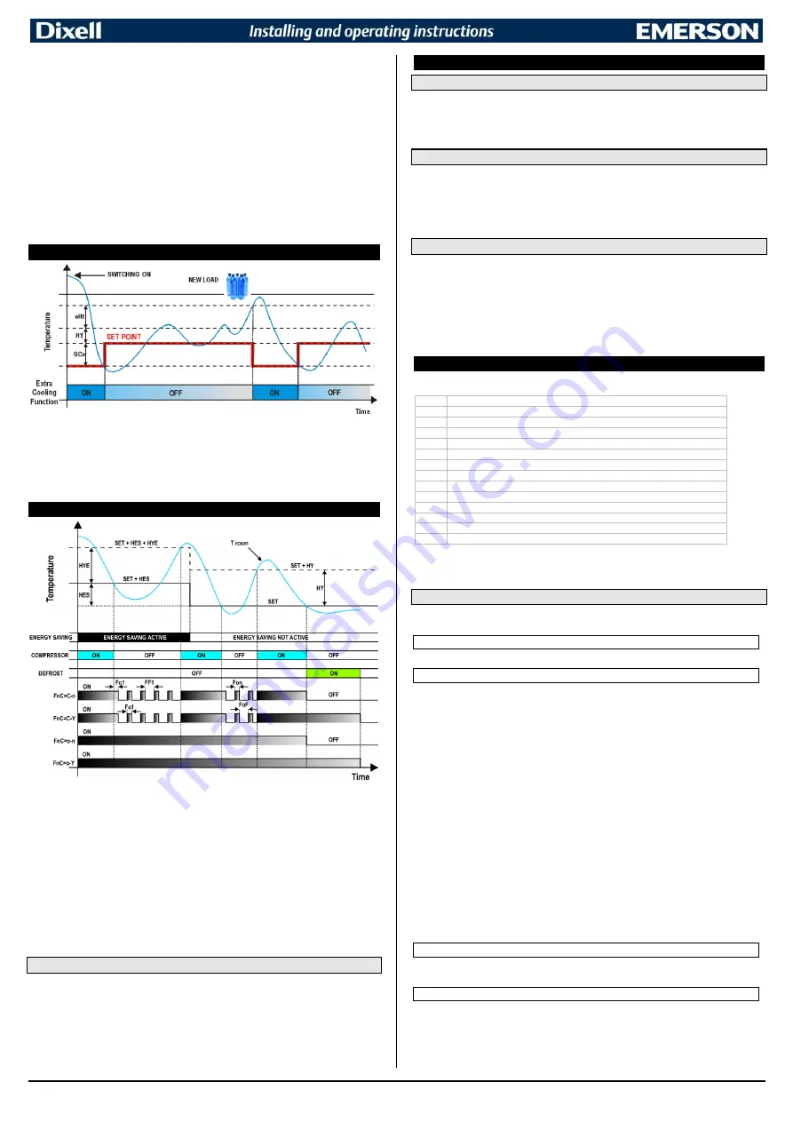
EXTRA COOLING FUNCTION
The extra cooling function (named Pull Down) is active when the room temperature measured from the probe
1 goes over the
SET+oHt+HY
value. In this case, a special set-point value, lower than the normal
SET
value,
will be enabled. As soon as the room temperature reaches the
SET+CCS
value, the compressor will be
stopped and the normal regulation will restart.
N.B.:
pull down function is disabled when
CCS=0
or
CCt=0
.
The
CCt
parameter sets the maximum activation time for any pull down. When
CCt
expires, the pull down will
be immediately stopped and the standard SET-POINT will be restored.
NOTE:
in case of energy saving mode
active, the used values will be:
SET_ES=SET+HES, oHE
and
CCS.
6
EVAPORATOR FANS
With
FnC
parameter it can be selected the fans functioning:
•
FnC=C-n
fans will switch ON and OFF with the compressor and
not run
during defrost; when
compressor is OFF, fans will enter a duty-cycle working mode (see
FoF
,
Fon
,
FF1
and
Fo1
parameters).
•
FnC=o-n
fans will run even if the compressor is off, and not run during defrost;
•
FnC=C-Y
fans will switch ON and OFF with the compressor and
run
during defrost; when
compressor is OFF all fans will enter a duty-cycle working mode (see
FoF
,
Fon
,
FF1
and
Fo1
parameters).
•
FnC=o-Y
fans will run continuously also during defrost.
After defrost, there is a timed fan delay allowing for drip time, set by means of the
Fnd
parameter.
An additional parameter
FSt
provides the setting of temperature, detected by the evaporator probe,
above which the fans are always OFF. By using this parameter it is possible to assure air circulation
only if air temperature is lower than
FSt
value.
6.1
EVAPORATOR FAN AND DIGITAL INPUT
When the digital input is configured as door switch (
i1F=dor
), fans and compressor status will depend on the
odC
parameter value:
•
odC=no
normal regulation
•
odC=FAn
evaporator fan OFF
•
odC=CPr
compressor OFF
•
odC=F-C
compressor and evaporator fan OFF
When
rrd=Y
the regulation will restart after a door open alarm.
7
DEFROST
7.1
DEFROST MODE
Any defrost operation can be controlled in the following way:
-
EdF=rtC
: by using an internal real time clock (only for models equipped with RTC).
-
EdF=in
: timed defrost, in this case a new defrost will start as soon as the idF timer elapses.
-
EdF=Aut
: automatic management, in this case the controller will start a new defrost any time a
change from normal to energy saving mode will occur (valid if
ErA=Aut
).
7.2
TIMED OR PROBE CONTROLLED MODE
Two defrost modes are available
: timed or controlled by the evaporator’s probe.
A couple of
parameters is used to control the interval between defrost cycles (
idF
) and its maximum length (
MdF
).
During the defrost cycle is possible to select some different display indications by using the
dFd
parameter. These modes are available with any kind of defrost type:
-
tdF=EL
: electric heater defrost
-
tdF=in
: hot gas defrost.
7.3
AUTOMATIC DURATION DETECTION
When a defrost operation is performed by compressor stop (means by stopping the compressor and by
activating the internal ventilators), it will be possible to use an automatic defrost mode by setting
od2=ALt
. In
this case the device will use the evaporator probe (which MUST to be present and properly mounted on the
evaporator surface) to detect the end of the actual defrost phase. In any case, a maximum period of time
(
MdF
) and an upper evaporator temperature value will be used to stop the current defrost phase. If
ErA=Aut
,
the automatic defrost mode will activate a defrost at the beginning of any energy saving mode period. In this
case the
idF
delay is used as safety function. It forces the controller to activate a defrost operation when
idF
runs.
NOTE:
during the defrost phase the loads (compressor and evaporator fans) will be controlled from the
defrost algorithm.
8
INTERNAL COUNTERS
The next table shows the implemented load and function of total counters.
n1H
Number of relay output 1 activation (thousands of)
n1L
Number of relay output 1 activation (hundreds of)
n2H
Number of relay output 2 activation (thousands of)
n2L
Number of relay output 2 activation (hundreds of)
n3H
Number of relay output 3 activation (thousands of)
n3L
Number of relay output 3 activation (hundreds of)
n4H
Number of relay output 4 activation (thousands of)
n4L
Number of relay output 4 activation (hundreds of)
n5H
Number of digital input 1 activation (thousands of)
n5L
Number of digital input 1 activation (hundreds of)
n6H
Number of digital input 2 activation (thousands of)
n6L
Number of digital input 2 activation (hundreds of)
oCH
Compressor working hours (thousands of)
oCL
Compressor working hours (hundreds of)
In this way it is possible to monitor the application and discovering bad functioning that could lead to damages.
They are updated in EEPROM every hour. It is not possible to reset them.
NOTE: the compressor activation counters take into account also defrost in case of inversion (hot gas) mode.
8.1
AUX RELAY CONFIGURATION (PAR. oAX)
An auxiliary relay can be set by the
oAx
parameters, according to the kind of application. In the
following paragraph the possible settings.
8.1.1
Light relay
With
oAx=LiG
the AUX relay operates as light output.
8.1.2
Auxiliary relay
a.
Relay activation by digital input 1 or digital input 2 (oAx=AUS, i1F or i2F=AUS):
with
oAx=AUS
and
i1F, i2F=AUS
the AUX relay is switched on and off by digital inputs.
b.
Auxiliary thermostat:
anti condensing heater with the possibility of switching it on and off also
by using the frontal keyboard.
Parameters involved:
-
ACH:
kind of regulation for the auxiliary relay:
Ht
= heating;
CL
=
cooling.
-
SAA:
set point for auxiliary relay.
-
SHy:
differential for auxiliary relay.
-
ArP:
probe for auxiliary relay.
-
Sdd:
auxiliary output off during defrost.
-
Ao1:
output active when in energy saving mode
-
AF1:
output not active when in energy saving mode
The differential threshold value is set by the
SHY
parameter.
NOTE:
if
oAx=AUS
and
ArP=nP
(no probe for auxiliary output) the AUX relay can be activated
-
by digital input if
i1F=AUS
or
i2F=AUS
-
by auxiliary button (if set as
AUS
)
-
by serial command (Modbus protocol)
-
by fixed interval of time if
Ao1>0
and
AF1>0
(if
Ao1=0
or
AF1=0
the auxiliary output is
disabled)
8.1.3
On/off relay (oAx = onF)
When
oAx=onF
, the AUX relay is activated when the controller is turned on and de-activated when
the controller is turned off.
8.1.4
Neutral zone regulation
With
oAx=db
the AUX relay can control a heater element to perform a neutral zone action.
•
oA1
cut in =
SET-HY
•
oA1
cut out =
SET


