D7.8.4/0112-0415/E
11/17
4.2
Terminal box and current sensing transformer connections
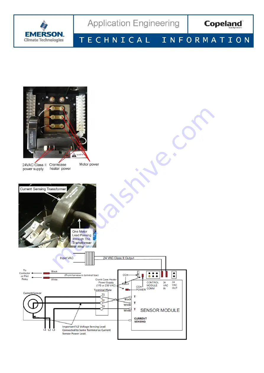
Make sure that the black lead from the sensor module is always connected to terminal 2 (factory-installed). Black
lead from sensor module must always be connected to that terminal of which power supply cable is lead through
current sensor.
4.2.1 Installation of current sensing module
One of the motor power leads passes through the “toroid” (current
sensing module). Information from the current sensing module is used
to determine running amps, power consumption and locked rotor
conditions. There are 3 voltage sensing leads attached to the motor
terminals and connected to the sensor module. Two of the leads are
white, and one is black. For proper calculation of power factor and motor
power it is necessary for the black voltage sensing lead and the power
lead through the current sensing module to be connected to the same
motor terminal.
The sensor module needs 3VA (Volt-Ampere) and a 24V AC power
supply. Therefore a Class II transformer must be used. Class II
transformers have a maximum rating of less than 100VA and a
maximum secondary output of 30V AC.
Figure 11: Current sensing module and T-Box wiring
4.2.2 CoreSense Diagnostics with
Υ/Δ motors
The t
erminal box and the current sensing “toroid” connections are
factory-installed. One of the motor power leads must be routed through
the centre opening of the current sensing transformer (see
Figures 12 &
13
below).
Figure 12: Current sensing transformer
Figure 13: Wiring sensor module and leads routed through the current sensor


