AGL_HP_ST_ZHK1P_EN_Rev00
29
6
Maintenance & repair
WARNING
Conductor cables! Electrical shock!
Follow the lockout/tag out proc edure
and the national regulations before carrying out any maintenance or serv ic e
work on the system.
Use compressor with grounded system only. Screwed electrical connections
must be used in all applications. Refer to original equipment wiring diagrams.
Electrical connections must be made by qualified electrical personnel.
6.1 Exchanging the refrigerant
CAUTION
Low suction pressure operation! Compressor damage!
Do no t operat e
with a restricted suction. Do not operate with the low-pressure limiter
bridged. Do not operate compressor at pressures that are not allowed by the
operating envelope. Allowing the suction pressure to drop below the
envelope limit for more than a f ew seconds may overheat scrolls and c ause
early drive bearing and moving parts damage.
For qualified refrigerants and oils, see
section 3.6.1
.
It is not necessary to replace the refrigerant unless contamination, for example due to an error such
as topping up the system with a non-condensable gas or incorrect refrigerant , is suspec ted. To
verif y correct refrigerant composition, a sample can be taken for chemical analysis. A check can be
made during shutdown by comparing the refrigerant temperature and p ress ure us ing prec is ion
measurements at a location in the system where liquid and vapour phases are present and when
the temperatures have stabilised.
6.2 Rotalock valves
Rotalock valves should be periodically re-torqued to ensure that leak tightness is maintained.
6.3 Disassembling system components
When disassembling system components please follow the main steps described hereunder:
1.
Recover ref rigerant and evacuate system using a recovery unit and vac uum pump. A ll the
ref rigerant shall be recovered to avoid significant release.
2.
Flush system with inert gas (dry nitrogen). Compressed air or oxygen s hall n o t b e us ed f or
purging refrigerant systems.
3.
Disassemble components with a cutting tool.
4.
Drain, recover and dispose of compressor oil as
appropriate.
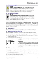
To disconnect:
▪
Using a pipe cutting tool, cut off the suction and discharge
lines in such a manner that the new compressor can easily b e
re-connected into the system.
▪
Heat joint areas 2 and 3 slowly and unif ormly until the
braze material sof tens and the tube end can be pulled out
f rom the fitting.
To reconnect:
▪
Recommended brazing material: Silfos with minimum 5 % silver or silver braze us ed on o ther
compressors.
▪
Due to the different thermal properties of steel and copper, brazing procedures may have t o be
changed from those commonly used.
NOTE: Since the discharge stub contains a check valve, care must be taken not to overheat
it to prevent brazing material from flowing into it.
Figure 25: Tube connecting areas

