


AGL_HP_ST_ZHK1P_EN_Rev00
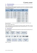
13
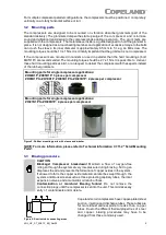
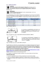
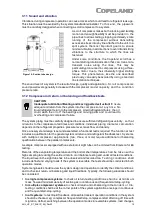
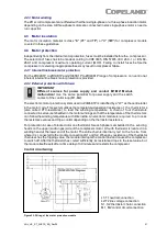
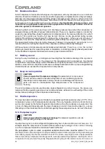
Figure 12: Sketch of discharge gas temperature protection for compressors with external sensor
For compressors ZHI18K1P and ZHI23K1P tandem-ready BOM 477 and f or compressors
ZHI27K1P to ZHI46K1P, the maximum discharge gas temperature is 135°C. These c ompres sors
are equipped with a NTC-temperature sensor in the top cap
– see
Figure 13
. This sensor
measures the discharge gas temperature in the top cap and must be connected to the cont roller,
eg, EXD TEVI (contact Emerson for more information). The controller has to stop the compressor
when the maximum discharge gas temperature is exceeded.
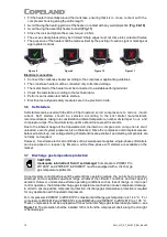
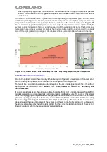
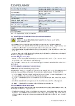
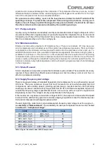
Figure 13: NTC sensor in top cap and resistance values for compressors ZHI18K1P and ZHI23K1P tandem ready
BOM 477 and ZHI27K1P to ZHI46K1P
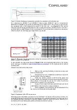
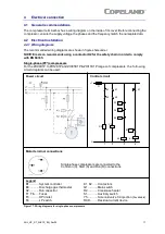
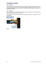
In case the NTC top cap sensor shown in
Figure 13
has to be replaced please refer to t he S pare
f or the replacement kit with all
needed parts.
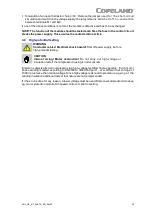
Please f ollow instructions hereunder:
▪
Remove the existing thermally conductive compound
f rom the thermal well.
▪
Dispense 0.75-1 cm
3
of thermally conductive compound
into the bottom of the thermal well.
▪
Clean any debris, grease or dirt f rom the upper cap
surf ace outside the thermistor tube opening along with the inside
tube surf ace. If the areas shown are not clean, the silicone
sealant will not adhere to the compressor.
▪
Apply a 5 mm bead of silicone sealant (Copeland ident
nr 8413046) on the thermistor in areas indicated.
▪
Af ter installation, the thermistor must be flushed with t he
top cap on, and the seal must be watertight.
Figure 14: Replacement of the NTC top cap sensor
Discharge gas temperature protection is the "f all-back" f or f ailure of the system control. It is
essential that proper control of both the evaporating and condensing pressures and the superheat
is maintained and has the ability to cope with all likely conditions and hig h lo ads. Reliance o n
protectors will cause inadequate system performance and short cycling.
Temperature
in °C
Resistance
in K
Ω
Temperature
in °C
Resistance
in K
Ω
-40
2889.60
80
10.79
-30
1522.20
90
7.87
-20
834.72
100
5.85
-10
475.74
110
4.45
0
280.82
120
3.35
10
171.17
130
2.58
20
107.44
140
2.02
25
86.00
150
1.59
30
69.28
160
1.25
40
45.81
170
1.01
50
30.99
180
0.83
60
21.40
190
0.68
70
15.07
-
-
Spring coil


