background image

21

© 2015  Emerson Climate Technologies, Inc.

AE4-1400 R1

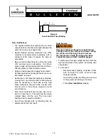
Figure 8 – Suction Funnel Diagram

Sucon Funnel 

Sucon Tube 

Back Of 

Funnel 

Oil Drain 

Hole 

Typical Funnel


Summary of Contents for Copeland Scroll ZP K6 Series

Page 1: ...haracteristics 9 PTC Start Components 9 Electrical Connections 9 Deep Vacuum Operation 9 Suction Discharge Fittings 9 System Tubing Stress 9 Three Phase Scroll Electrical Phasing 10 Brief Power Interruptions 10 Tandem Compressors 10 Maximum Tilt Angle 10 Application Tests Application Summary 10 Continuous Floodback Test 11 Field Application Test 11 Assembly Line Procedures Installing the Compresso...

Page 2: ...ssor You are strongly advised to follow these safety instructions Safety Icon Explanation DANGER indicates a hazardous situation which if not avoided will result in death or serious injury WARNING indicates a hazardous situation which if not avoided could result in death or serious injury CAUTION used with the safety alert symbol indicates a hazardous situation which if not avoided could result in...

Page 3: ...ipment must be used Failure to follow these warnings could result in serious personal injury BURN HAZARD Do not touch the compressor until it has cooled down Ensure that materials and wiring do not touch high temperature areas of the compressor Use caution when brazing system commponents Personal safety equipment must be used Failure to follow these warnings could result in serious personal injury...

Page 4: ...or It is designed to open when the discharge to suction pressure differential exceeds 550 to 625 psid 38 43 bar When the valve opens hot discharge gas is routed back into the area of the motor protector to cause a trip During fan failure testing system behavior and operating pressures will depend on the type of refrigerant metering device Fixed orifice devices may flood the compressor with refrige...

Page 5: ... Some systems such as air to air heat pumps may not work with the above low pressure control arrangement A discharge line thermostat set to shut the compressor off before the discharge temperature exceeds 260º F 125ºC may have to be used to achieve the same protection Mount the discharge thermostat as close as possible to the compressor discharge fitting and insulate well See Table 5 for recommend...

Page 6: ...tion to the compressor bearings The size of the accumulator depends upon the operating range of the system and the amount of sub cooling and subsequent head pressure allowed by the refrigerant control System modeling indicates that heat pumps that operate down to and below 0 F 18 C will require an accumulator that can hold around 70 to 75 of the system charge Behavior of the accumulator and its ab...

Page 7: ...re valve shifting must be measured throughout the operating range of the unit and compared to the valve manufacturer s data Low ambient heating conditions with low flow rates and low pressure drop across the valve can result in a valve not shifting This can result in a condition where the compressor appears to be not pumping i e balanced pressures It can also result in elevated compressor sound le...

Page 8: ...cycle can trap significant quantities of oil if system piping allows the oil to fall out of the refrigerant flow into an inactive circuit The oil level must be carefully monitored during system development and corrective action should be taken if compressor oil level falls below the top of the lower bearing bracket for more than two minutes The lower bearing bracket weld points on the compressor s...

Page 9: ...e starting for any of these compressors SecureStart is marketed and sold by Emerson Climate Technologies Inc to reduce inrush current by up to 75 on single phase Copeland Scroll compressors SecureStart significantly reduces inrush and associated light dimming while offering a number of other protective benefits For more information on SecureStart please refer to AE8 1370 Electrical Connections WAR...

Page 10: ...al overload resets the compressor will start and run normally To avoid disruption of operation an electronic control that can sense brief power interruptions may be used to lock out the compressor for a short time This control could be incorporated in other system controls such as defrost control board or the system thermostat or can be a stand alone control Functional specifications for this cont...

Page 11: ...ducing refrigerant charge decreasing capillary or orifice diameter and adding a charge compensator can also be used to reduce excessive continuous liquid refrigerant flood back Field Application Test To test for repeated excessive liquid flood back during normal system off cycles perform the Field Application Test that is outlined in Table 2 Obtain a sample compressor with a sight tube to measure ...

Page 12: ...cting capillary tubes thermal expansion valves and accumulator oil return holes Any blockage of oil or refrigerant may damage the compressor resulting in failure Pressure Testing WARNING Never pressurize the compressor to more than 475 psig 32 8 bar for leak checking purposes Never pressurize the compressor from a nitrogen cylinder or other pressure source without an appropriately sized pressure r...

Page 13: ...oltage sag during starting the first compressor in a production run should be used to preset the voltage Remove the start wire from the compressor and apply 200 volts to the compressor With the start winding removed the compressor will remain on locked rotor long enough to read the supply voltage If the voltage sags below the minimum guaranteed starting voltage the variable transformer must be res...

Page 14: ...e conventional three phase motors with equal resistances in each winding 9 Before replacing or returning a compressor be certain that the compressor is actually faulty As a minimum recheck compressors returned from the field in the shop or depot by testing for a grounded open or shorted winding and the ability to start The orange tag in the service compressor box should be filled out and attached ...

Page 15: ...C Condensing Temperature C Condensing Temperature F Evaporating Temperature F Note PFV Voltage Tolerance 10 to 5 Figure 1 R 410A Scroll Operating Envelope it unattended with no charge a holding charge or with the service valves closed without securely locking out the system This will prevent unauthorized personnel from accidentally ruining the compressor by operating with no refrigerant flow ...

Page 16: ...ise superheat A cold sump may result in high refrigerant migration after shut down Figure 2 Oil Dilution Chart 30 25 20 15 10 5 0 5 10 24 14 4 6 16 26 36 10 0 10 20 30 40 50 60 70 80 90 100 110 20 10 0 10 20 30 40 50 Evaporating Temperature C Compressor Sump Temperature C Compressor Sump Temperature F Evaporating Temperature F 200 F 93 3 C Max Oil Temp Acceptable Unacceptable Too Much Refrigerant ...

Page 17: ...ostat if used Compressor Contactor Other Protective Devices if used System Operating Thermostat Fuse A B Time Delay Relay Specifications Timer Opens 1 Electrical Cycle Timer Closes Greater than 5 seconds later whether 016 Sec With 60 HZ Operation power is restored or not after power is removed Figure 4 Compressor Electrical Connection T1 C T2 S T3 R ...

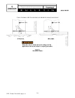
Page 18: ...am Weld Seam Weld Figure 5 Crankcase Heater ZP10 31K6 ZP34 54K6 WARNING Verify the correct crankcase heater voltage for the application and ensure heater is properly grounded Connect the heater so that the connection point straddles the compressor seam weld ...

Page 19: ... Add braze material to the joint while moving torch around joint to flow braze material around circumference After braze material flows around joint move torch to heat Area 3 This will draw the braze material down into the joint The time spent heating Area 3 should be minimal As with any brazed joint overheating may be detrimental to the final result Field Service WARNING Remove refrigerant charge...

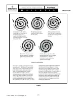
Page 20: ...20 2015 Emerson Climate Technologies Inc AE4 1400 R1 Figure 7 ...

Page 21: ...21 2015 Emerson Climate Technologies Inc AE4 1400 R1 Figure 8 Suction Funnel Diagram Suc on Funnel Suc on Tube Back Of Funnel Oil Drain Hole Typical Funnel ...

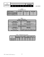
Page 22: ...g Configuration Shock loop Service Valve Angled valve fastened to unit Suction muffler Not required Alternate Configuration Component Description Tubing Configuration Shock loop Service Valve Straight through valve not fastened to unit Mass Suction muffler May be required Acts as dampening mass Table 3 Design Configurations Table 4 Refrigerant Charge Limits Model Compressor Charge Limit System Cha...

Page 23: ... SecureStart 943 0120 00 All Models 1 Phase Only CoreSense Diagnostics Module 971 0066 00 All Models 2 Wire Module 1 Phase Only CoreSense Diagnostics Module 971 0067 00 3 Wire Module 1 Phase Only Comfort Alert Module 543 0010 01 2 Wire Module 1 Phase Only Comfort Alert Module 543 0032 00 1 Phase Only Has L Terminal Comfort Alert Module 543 0038 02 3 Phase Only Comfort Alert Module 543 0067 00 1 Ph...

Reviews: