C6.1.7/1110-0519/E
13
3.4 Electrical connections
3.4.1 Power supply connections
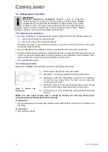
The electrical connection of the HLR Digital Receiver unit to the power supply must be made by
qualified technicians; the electrical diagrams are located inside the electrical connection box.
Figure 9: Electrical connection box
3.4.2 Pre-wired electrical components
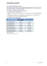
Electrical connections should be made with great care to avoid reverse rotation.
Pre-wired electrical
components
Single compressor units
HLR13-ZBD30KCE HLR13-ZBD45KCE HLR13-ZBD58KCE HLR13-ZBD76KCE
Compressor contactor
18 A
18 A
25 A
25 A
Overload protector
6 to 10 A
9 to 14 A
13 to 18 A
17 to 23 A
Fuses
2
2
2
2
Electronic controller
EC2-552
EC2-552
EC2-552
EC2-552
Crankcase heater
1
1
1
1
HP/LP Pressure switch PS2
1
1
1
1
HP Pressure switch PS3
–
–
–
–
LP Pressure switch PS1
–
–
–
–
Digital 24V solenoid valve
1
1
1
1
Table 7: Electrical connections
– Single compressor units
Pre-wired electrical
components
Tandem-compressor units
HLR13-ZBDT60KCE
HLR13-ZBDT90KCE
HLR31-ZBDT116KCE HLR31-ZBDT152KCE
Compressor contactor
2 x 25 A
2 x 25 A
2 x 25 A
2 x 25 A
Overload protector
2 x (9 to 14 A)
2 x (9 to 14 A)
2x (13 to 18 A)
2x (17 to 23 A)
Fuses
2
2
2
2
Electronic controller
EC2-552
EC2-552
EC2-552
EC2-552
Crankcase heater
2
2
2
2
HP/LP Pressure switch PS2
–
–
–
–
HP Pressure switch PS3
2
2
2
2
LP Pressure switch PS1
1
1
1
1
Digital 24V solenoid valve
1
1
1
1
Table 8: Electrical connections
– Tandem-compressor units
Contactor K1
Circuit breaker
Auxiliary relay K10
Fuses F1, F2
Transformer T1


