background image

63

Specifications

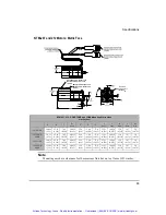
NTM-207 and 212 Motors; Metric Face

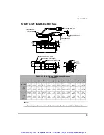
Note

Mounting ears have clearance for 10mm across flats hex nut or 13mm O.D. washer.

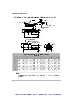
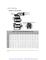
NTM-207, 212 -CONS,TONS and LONS Mounting Dimensions

mm (inches)

A

B

C

D

Max

E

F

G

I

Max

J

Max

K

Min

L

Min

M

Min

207-CONS

140.96

(5.55)

65.18

(2.566)

7.49

(0.295)

60.012

(2.363)

2.54

(0.10)

5.80

(0.228)

75.0

(2.953)

23.51

(0.926)

10.999

(0.433)

13.0

(0.512)

3.97

(0.156)

2.0

(0.079)

207-TONS/

LONS

111.51

(4.39)

65.18

(2.566)

7.49

(0.295)

60.012

(2.363)

2.54

(0.10)

5.80

(0.228)

75.0

(2.953)

23.51

(0.926)

10.999

(0.433)

13.0

(0.512)

3.97

(0.156)

2.0

(0.079)

212-CONS

166.36

(6.55)

65.18

(2.566)

7.49

(0.295)

60.012

(2.363)

2.54

(0.10)

5.80

(0.228)

75.0

(2.953)

23.51

(0.926)

10.999

(0.433)

13.0

(0.512)

3.97

(0.156)

2.0

(0.079)

212-TONS/

LONS

136.91

(5.39)

65.18

(2.566)

7.49

(0.295)

60.012

(2.363)

2.54

(0.10)

5.80

(0.228)

75.0

(2.953)

23.51

(0.926)

10.999

(0.433)

13.0

(0.512)

3.97

(0.156)

2.0

(0.079)

1.780 [45.21]

MAX

1.925 [48.89]

MAX

A

ENCODER CONN: PT02E-16-23P
MATING CONN: PT06E-16-23S

(-CONS)

MOTOR CONN: PT02E-16-8P
MATING CONN: PT06E-16-8S

(-CONS)


DRILLED 

THRU (4) EQUALLY 

SPACED ON


G

Artisan Technology Group - Quality Instrumentation ... Guaranteed | (888) 88-SOURCE | www.artisantg.com

Summary of Contents for Control Techniques EN Series

Page 1: ...derutilized and idle equipment along with credit for buybacks and trade ins Custom engineering so your equipment works exactly as you specify Critical and expedited services Leasing Rentals Demos In stock Ready to ship TAR certified secure asset solutions Expert team I Trust guarantee I 100 satisfaction All trademarks brand names and brands appearing herein are the property of their respective own...

Page 2: ...tallation Manual P N 400501 02 Revision A5 Date January 10 2003 Control Techniques Drives Inc 1999 2003 EN Drives Artisan Technology Group Quality Instrumentation Guaranteed 888 88 SOURCE www artisantg com ...

Page 3: ...Artisan Technology Group Quality Instrumentation Guaranteed 888 88 SOURCE www artisantg com ...

Page 4: ...n of the equipment described herein and any associated motion products without notice Control Techniques also assumes no responsibility for any errors that may appear in this document Information in this document is subject to change without notice P N 400501 02 Revision A5 Date January 10 2003 Control Techniques Drives Inc 1999 2003 EN Drives Installation Manual Artisan Technology Group Quality I...

Page 5: ... of Emerson Electric Co Control Techniques is not affiliated with Microsoft Corporation owner of the MicroSoft Windows and Windows NT trademarks IBM is a registered trademark of International Business Machines Inc Modbus is a trademark of Gould Inc Data Highway Plus is a trademark of Allen Bradley Schaffner is a trademark of Schaffner DeviceNet is a trademark of Open DeviceNet Vendor Association T...

Page 6: ...al notes frequently asked questions release notes and other technical documentation This direct technical support connection lets you request assistance and exchange software files electronically Technical Support 952 995 8033 or 800 397 3786 Email service emersonct com Control Techniques Motion Made Easy products are backed by a team of professionals who will service your installation Our technic...

Page 7: ...or tough or complex applications Our engineers offer you a broad base of experience and knowledge of electronic motion control applications Customer Service Sales 952 995 8000 or 800 397 3786 Email customer service emersonct com Authorized Control Techniques distributors may place orders directly with our Customer Service department Contact the Customer Service department at this number for the di...

Page 8: ... drive specifically Throughout this manual the word drive refers to an EN drive This Represents bold Characters that you must type exactly as they appear For example if you are directed to type a setup you should type all the bold characters exactly as they are printed italic Placeholders for information you must provide For example if you are directed to type filename you should type the actual n...

Page 9: ...its and equipment in accordance with established safety practices Is trained in the proper care and use of protective equipment in accordance with established safety practices Is trained in rendering first aid Reference Materials The following related reference and installation manuals may be useful with your particular system PowerTools Software User s Guide P N 400503 01 FM 1 Speed Module Refere...

Page 10: ...y degree above 40 C 104 F This product is suitable for use on a circuit of delivering not more than 5000 RMS symmetrical amperes 240 volts maximum Motors must incorporate an overload protection device such as an overtemperature switch Drive Overload Protection The drive output current overload protection is provided by the drive and is not adjustable This overload protection is based on maximum co...

Page 11: ...l indicates that this product meets safety and noise immunity and emissions EMC standards when installed according to the installation guidelines and used within the product specifications Drive Output Current vs Time graph 0 10 20 30 40 50 60 100 125 150 175 200 Drive Rated Current Time seconds Artisan Technology Group Quality Instrumentation Guaranteed 888 88 SOURCE www artisantg com ...

Page 12: ... 15 80 MHz ENV 50204 1995 Pulse 900 MHz 50 DTY 200 Hz Supplementary information The products herewith comply with the requirements of the Low Voltage Directive LVD 73 23 EEC and EMC Directive 89 336 EEC This electronic drive product is intended to be used with an appropriate motor electrical protection components and other equipment to form a complete end product or system It must only be installe...

Page 13: ...uct is intended to be used with an appropriate motor electrical protection components and other equipment to form a complete end product or system It must only be installed by a professional assembler who is familiar with requirements for safety and electromagnetic compatibility EMC The assembler is responsible for ensuring that the end product or system complies with all the relevant laws in the ...

Page 14: ...on conducting contamination is acceptable Setup Commissioning and Maintenance It is essential that you give careful consideration to changes to drive settings Depending on the application a change could have an impact on safety You must take appropriate precautions against inadvertent changes or tampering Restoring default parameters in certain applications may cause unpredictable or hazardous ope...

Page 15: ... A special hazard may exist where the drive is incorporated into a product which is connected to the AC supply by a plug and socket When unplugged the pins of the plug may be connected to the drive input which is only separated from the charge stored in the bus capacitor by semiconductor devices To avoid any possibility of electric shock from the pins if they are accessible a means must be provide...

Page 16: ... Feedback Wiring 20 Motor Brake Wiring 21 Command Connector J5 Wiring 24 Serial Communications 32 Diagnostics and Troubleshooting 35 Diagnostic Display 35 Fault Codes 36 Diagnostic Analog Output Test Points 40 Drive Faults 42 Watch Window 42 View Motor Parameters 44 Error Messages 44 Specifications 47 Drive Specifications 47 Drive and Motor Combination Specifications 50 Motor Brake Specifications ...

Page 17: ...tion 53 Speed Torque Curves 55 EN Drive Dimensions 59 MG Motor Dimensions 60 NT Motor Dimensions 62 Motor Wiring Color Cable 67 Cable Diagrams 68 Glossary 81 Index 87 Artisan Technology Group Quality Instrumentation Guaranteed 888 88 SOURCE www artisantg com ...

Page 18: ...ng and a single home routine FM 3 FM 3DN and FM 3PB Programming Modules offer complex motion profiling A complex motion profile consists of two or more indexes that are executed in sequence such that the final velocity of each index except the last is non zero Logical instructions between index statements can provide a powerful tool for altering motion profiles on the fly FM 4 FM 4DN and FM 4PB Pr...

Page 19: ...d encoder feedback for accurate positioning Drive Model Power Rating Continuous Current Peak Current EN 204 1750 W 4 5 A RMS 9 0 A RMS EN 208 2750 W 9 0 A RMS 18 0 A RMS EN 214 4340 W 13 A RMS 26 A RMS EN Drive Command Connection J5 AC Power Input J1 Feedback Connection J7 Drive Reset Button Bus Power Connection J2 Auxiliary Power Connection J3 Motor Power Connection J8 Input Output Terminals J6 S...

Page 20: ...antee your system will meet tested emission or immunity requirements If you need to meet EMC compliance requirements EMI RFI line filters must be used to control conducted and radiated emissions as well as improve conducted immunity Physical location of these filters is very important in achieving these benefits The filter output wires should be kept as short as possible 12 inches is suggested and...

Page 21: ...h corrosion which will hinder the low impedance connection Enclosure manufacturers offer corrosion resistant unpainted mounting plates to help Bringing components into direct contact cannot always be achieved In these situations a conductor must be relied upon to provide a low impedance path between components Remember a flat braided wire has lower impedance than a round wire of a large gauge rati...

Page 22: ...ilter inputs routed away from any electrical noise sources to prevent noise from being induced into them and carried out of the enclosure Cable to Enclosure Shielding Shielded motor feedback serial communications and external encoder cables were used for Control Techniques compliance testing and are necessary to meet the EMC requirements Each cable shield was grounded at the enclosure wall by the ...

Page 23: ... 7 8 Motor Cable 12 Ga CMMS CGS 050 1 2 pipe 7 8 Feedback Cable CFOS CGS 050 1 2 pipe 7 8 Flex Motor Cable 16 Ga CMDF CGS 050 1 2 pipe 7 8 Flex Motor Cable 12 Ga CMMF CGS 075 3 4 pipe 1 1 16 Flex Feedback Cable CFCF CFOF A CGS 063 3 4 pipe 1 1 16 External Encoder ENCO CGS 038 1 2 pipe 7 8 AC Power user supplied user supplied user supplied user supplied Artisan Technology Group Quality Instrumentat...

Page 24: ...5 or 1 1 8 CFOF A CGS 069 1 125 or 1 1 8 MGFF CGS 069 1 125 or 1 1 8 External Encoder ENCO CGS 047 0 8125 or 13 16 After tighten lock nut and positioning cable so that spring contacts are contacting the cable shield tighten cable seal housing Remove 1 2 to 1 inches of cable jacket The Spring Contacts will make a continuous electrical path from the shield of the cable to equipment ground When Lock ...

Page 25: ... the thermal transfer of the enclosure to the ambient air and the amount of power being dissipated inside the enclosure Consult your enclosure manufacturer for assistance with determining cooling requirements NEMA Enclosure This wail must have good continuity to enclosure ground Through wall shield grommets External Encoder CMDS or CMMS Cable CFOS Cable CFOS Cable CMDS or CMMS Cable CFCO Cable Cus...

Page 26: ... that metal to metal contact is made between the enclosure ground lug and the metal enclosure not simply through the mounting bolt and threads All inductive coils must be suppressed with appropriate devices such as diodes or resistor capacitor RC networks Mechanical Installation Drive Mounting Drives must be back mounted vertically on a metal surface such as a NEMA enclosure A minimum spacing of t...

Page 27: ... must be removed from mounting surface to assure the chassis of the drive is connected to the single point ground DC Power Supply Enclosure Wall Mains Contactor AC Line Fuses 3 Phase Line Power 24 VDC User Supply N Paint must be removed at least from behind the mounting tab Single Point Ground Ground connection rail and enclosure panel should have a low impedance connection Paint must be removed f...

Page 28: ...xceed 264 VAC phase to phase and phase to PE ground This can be accomplished by referencing the AC supply to earth ground Do not connect or disconnect the AC power by inserting or removing the AC power connector Using the connector in this manner even once will damage the connector making it unusable AC Supplies NOT Requiring Transformers If the distribution transformer is configured as shown in t...

Page 29: ...r is used between the power distribution point and the drives the transformer secondary must be grounded for safety reasons as shown in the figures below Figure 8 Three Phase Delta with mid phase GND Distribution to a Three Phase Delta WYE Isolation Transformer DISTRIBUTION PANEL SECONDARY L3 L2 230 VAC L1 PE Protective Earth EARTH GROUND To Fusing and Drive Terminals Artisan Technology Group Qual...

Page 30: ...ed Distribution to a Three Phase Delta WYE Isolation Transformer Figure 10 Delta to Delta Isolation Transformer Figure 11 Single Phase Power Supply Connections Artisan Technology Group Quality Instrumentation Guaranteed 888 88 SOURCE www artisantg com ...

Page 31: ...s velocity motion multiply the Continuous Power by 1 5 and select the closest transformer size greater than or equal to this result For applications that require positioning multiple starts and stops use a multiplier of 2 to determine the transformer size It is always better to oversize the transformer Transformer life is directly dependent on the temperature of the windings and if the transformer...

Page 32: ...r Connections According to UL requirements the EN drive is suitable for use on a circuit capable of delivering not more than 5000 RMS symmetrical amperes 240 volts maximum Drive Model External AC Line Fuse Recommended Minimum AC PE Line Wire Gauge EN 204 KTK R 15 Amp 1Ø 14 AWG EN 208 RK1 20 Amp 1Ø 12 AWG EN 214 RK1 20 Amp 3Ø 12 AWG Drive Model Input Voltage VAC Frequency Hz Input Current Amps RMS ...

Page 33: ...14 P47 If 12 AWG use Panduit PV10 P55 50 60 Hz 90 264 VAC Note L3 is used with the EN 214 only When cycling power make sure AC power is off for 5 seconds minimum before reapplying power L1 Tighten screws to 5 lb in L2 L3 GND J1 L1 L2 L3 PE Front View Artisan Technology Group Quality Instrumentation Guaranteed 888 88 SOURCE www artisantg com ...

Page 34: ...he reset button or a reset input after AC power is re applied if the backup supplies have been active Auxiliary Logic Power Usage Figure 13 EN Auxiliary Power Supply Wiring Diagram Top View V Bus Use 16 to 18 AWG stranded wire Bus J2 J3 Auxiliary Supply Auxiliary Supply J3 Two position header The mating ALPC 006 cable is supplied with the ALP Auxiliary Power Supply V Auxiliary Supply V Auxiliary S...

Page 35: ...out tab AC power must be disconnected for at least 30 seconds before removing the tab Motor Power Wiring MG and NT Motors are equipped with up to three male MS Military Standard connectors one for stator connections one for encoder connections and one for the brake if so equipped Stator connections from the drive to the motor are made with the CMDS or CMMS cable have a female MS style connector on...

Page 36: ...5 lb in Important Ground should connect to drive and motor only Nothing should be connected between these devices Front View Connector Shell R S T Ground Motor Power Connection Drive PE S B Shield Green Yellow Black T C Blue 2 or 3 Motors PT06A 15 8SSR 4 Motors MS3106A 20 15SSR D R Brown A GND Artisan Technology Group Quality Instrumentation Guaranteed 888 88 SOURCE www artisantg com ...

Page 37: ...th a part number of 960500 07 or lower can only accept differential U V W signals Note The indexing pulses A A B B Z and Z must come from a differential source Motor Motor Feedback Cable Model CFCS XXX Blue Orange Green Brown Black Yellow White Brown Brown White White Gray Gray White Red Orange Orange Red Red Blue Blue Red Red Green Green Red 13 15 17 16 1 10 11 2 3 12 4 5 14 6 7 9 8 18 19 26 R H ...

Page 38: ...ee the following wiring diagrams You must provide a DC power supply rated at 24 VDC with a 2 amp minimum current capacity for the brake If you use this voltage source to power other accessories such as I O or more than one brake you must increase its current capability Figure 16 EN Brake Wiring Diagram using the Command Connector Artisan Technology Group Quality Instrumentation Guaranteed 888 88 S...

Page 39: ...nes one is dedicated to a drive enable function and three optically isolated output lines They are designed to operate from a 10 to 30 VDC source All inputs and outputs are configured as sourcing You are responsible for choosing a load that will limit each output s current to less than 150 mA Artisan Technology Group Quality Instrumentation Guaranteed 888 88 SOURCE www artisantg com ...

Page 40: ... used Figure 19 EN I O Connector to Command Connector Internal Connections Front View I O supply 10 to 30 VDC 2 8 k Load Load Load A highspeed diode such as a 1N5819 is required for inductive loads such as a relay solenoid or contactor J6 24 VDC 1 Amp Fuse Single point PE ground Artisan Technology Group Quality Instrumentation Guaranteed 888 88 SOURCE www artisantg com ...

Page 41: ...0 multi axis controller simply connect the 44 pin connector of your AX4 CEN XXX cable to the drive and the 25 pin connector to the AXIMA multi axis controller If you are interfacing your drive s to an AXIMA or any other motion controller you may use either the CDRO XXX or CMDO XXX cables or the optional External Connection Interface ECI 44 which provides a convenient screw terminal connection stri...

Page 42: ...Channel Z Diagnostics Output Channel 1 Diagnostics Output Channel 2 Command Connector Do Not Connect Do Not Connect Do Not Connect Do Not Connect Do Not Connect Do Not Connect Do Not Connect Do Not Connect Shield PE 10 Ohm Connector Shell Connected to 15 Out Test Only Twisted Pair Pulse Input B Pulse Input B Pulse Input A Pulse Input A Pulse Input Z Pulse Input Z Pulse In B Single ended Pulse In A...

Page 43: ...le also reduces the enclosure spacing requirement below the drive For information about the CDRO XXX 13 pair cable wire colors see the Specifications section Function Pin Numbers Electrical Characteristics Inputs and Drive Enable 1 2 3 4 16 10 30 V On 0 3 V Off optically isolated Outputs 17 18 19 10 30 VDC sourcing 150 mA I O Supply 33 34 10 30 VDC 1 Amp maximum I O Common 31 32 I O return Pulse I...

Page 44: ...igure 21 Analog Command Differential Wiring Diagram Figure 22 Analog Command Single Ended Wiring Diagram Command Connector With positive direction CW Artisan Technology Group Quality Instrumentation Guaranteed 888 88 SOURCE www artisantg com ...

Page 45: ... encoder in the motor Figure 23 Command Connector Encoder Output Wiring Figure 24 Direction Convention Diagram If the external controller does not have an internal terminating resistor R1 R2 and R3 must be mounted within 6 inches of the external controller A 120 ohm resistor is recommended for high frequency encoders over 250 kHz or cables longer than 25 feet If encoder signals are multi dropped t...

Page 46: ...rnal controller does not have an internal terminating resistor R1 R2 and R3 must be mounted within 6 of the drive A 120 ohm resistor is recommended for high frequency over 250 kHz feedback signals or cable lengths longer than 25 feet Note Single Point PE Ground Twisted Pair Single Point Panel Ground Artisan Technology Group Quality Instrumentation Guaranteed 888 88 SOURCE www artisantg com ...

Page 47: ...e Figure 28 Pulse Mode Single Ended Output to Single Ended Input non twisted pair cable Common isolated from other sources Sinking Outputs typ Pulse A Direct B 5 Logic Power Common isolated from other sources Sinking Outputs typ Pulse A Direct B 5 Logic Power Artisan Technology Group Quality Instrumentation Guaranteed 888 88 SOURCE www artisantg com ...

Page 48: ...ntial pulse input is an RS 422 line receivers The default encoder Common isolated from other sources Sinking Outputs typ 5 Logic Power CW Pulse CCW Pulse CCW Pulse CW Pulse R1 R2 and R3 must be mounted within 6 of the end drive A 120 ohm resistor is recommended for high frequency over 250 kHz stepping or cable lengths longer than 25 feet Note Master Encoder or Drive Output Artisan Technology Group...

Page 49: ...he Serial Communication Connector When connecting the serial port of your PC to the serial port of the drive verify that your PC s ground is the same as the drive PE ground Failure to do so can result in damage to your PC and or your drive Note Communication errors can usually be avoided by powering the computer or host device off of a convenience outlet that is mounted in the enclosure and whose ...

Page 50: ... to 32 drives Control Techniques provides a special multi drop serial cable which allows you to easily connect two or more drives Figure 32 EN Multi Drop Wiring Diagram Serial Communications Specifications Max baud rate 19 2k Start bit 1 Stop bit 2 Parity none Data 8 Note The terminating resistor packs TERM H and TERM T should be installed on the first TERM H and last TERM T drive in the string if...

Page 51: ... 9 8 7 Drive Serial Port 3 4 5 6 2 1 9 8 7 Drive Serial Port TERM H TIA Cable DDS Cable DDS Cable TERM T 120 Ohm 120 Ohm 576 Ohm 576 Ohm 485 485 5 2 3 9 4 Computer Serial Port Drive Serial Port Drive Serial Port Drive Serial Port Top View of Multi drop Cabling TIA Cable DDS Cable DDS Cable TERM H TERM T Artisan Technology Group Quality Instrumentation Guaranteed 888 88 SOURCE www artisantg com ...

Page 52: ... Status Description Brake Engaged Output Off Motor brake is mechanically engaged This character will only appear if the Brake output function is assigned to an output line See Brake Operation section for detailed description of Brake Output function Disabled Power Stage is disabled Position Pulse mode operation Velocity Velocity mode operation Torque Torque mode operation Summation Summation mode ...

Page 53: ...ntinue to track the motor s position provided the logic power is not interrupted The Travel Limit faults are automatically cleared when the fault condition is removed The table below lists all the fault codes in priority order from highest to lowest This means that if two faults are active only the higher priority fault will be displayed Ready to Run Drive enabled no Stop input Display Fault Actio...

Page 54: ... Hardware Cycle Power Yes Motor Overtemp Allow Motor to cool down Reset Button or Input Line Yes RMS Shunt Power EN drives only Reset Button or Input Line Yes Overspeed Reset Button or Input Line Yes Following Error Pulse mode only Reset Button or Input Line Yes Travel Limit Auto No All On Normally On for one second during power up Yes Display Fault Action to Reset Bridge Disabled Artisan Technolo...

Page 55: ...witching transistor It can also occur if the drive enable input is cycled Off and On rapidly 10 Hz High DC Bus This fault will occur whenever the voltage on the DC bus exceeds the High DC Bus threshold The most likely cause of this fault would be an open external shunt fuse a high AC line condition or an application that requires an external shunt e g a large load with rapid deceleration Low DC Bu...

Page 56: ...one of two circumstances 1 When the actual motor speed exceeds the Overspeed Velocity Limit parameter or 150 of motor maximum operating speed This parameter can be accessed with PowerTools software 2 If the combination of command pulse frequency and Pulse Ratio can generate a motor command speed in excess of the fixed limit of 13000 RPM an Overspeed Fault will be activated In Pulse mode operation ...

Page 57: ... Analog Output Test Points The drive has two 8 bit real time Analog Outputs which may be used for diagnostics monitoring or control purposes These outputs are referred to as Channel 1 and Channel 2 They can be accessed from the Command Connector on the drive or from the Diagnostics Analog Output Pins located on the front of the drive Each Channel provides a programmable Analog Output Source Analog...

Page 58: ... other However if signals do get shorted to GND the drive will not be damaged because the circuitry is protected Figure 35 Diagnostic Cable DGNE Diagram Channel 2 Channel 1 Analog GND E Series Drive Epsilon Drive 10 Ohm 10 Ohm Yellow Black GND Blue D A D A DGNE Cable Command Connector DGNE Cable 2 GND 1 2 1 GND 44 29 43 Pin s Artisan Technology Group Quality Instrumentation Guaranteed 888 88 SOURC...

Page 59: ...h the Reset button on the front of the drive where the fault occurred Viewing Active Drive Faults To view all active drive faults select the View Faults command from the Device menu or by clicking on the View Faults icon on the toolbar The dialog box displayed is the same as Active Drive Faults Detected dialog box described above Rebooting the Drive To reboot the drive cycle power or select the Re...

Page 60: ...ed to view them simply push the Clear All button and select the parameters you wish to view Figure 37 Watch Window The Watch Window is accessed by selecting Watch Drive Parameters from the Tools menu or by clicking on the Watch Window icon on the toolbar The Watch Window will automatically appear as soon as you select a parameter from the Select Drive Parameters dialog box After you have selected ...

Page 61: ...tore Selections Button This button restores the parameter selections previously saved This enables you to restore the list of parameters you created in a previous online session View Motor Parameters When online with the drive this feature allows you to display a pre defined Watch Window to monitor three motor parameters These parameters are normally used when testing the setup of a User Defined M...

Page 62: ... This error is caused When you attempting to perform an upload or download to multiple drives and one or more of the drives are not the same type Disconnect the device s that has been specified and try the operation again or program each device individually You have changed a parameter which will not take affect until the drive has been rebooted Before you reboot the drive you will need to save yo...

Page 63: ...46 EN Drive Installation Manual Artisan Technology Group Quality Instrumentation Guaranteed 888 88 SOURCE www artisantg com ...

Page 64: ... EN 208 18 A EN 214 26 A for 1Ø derate by 20 Continuous Output Power EN 204 1 8 kW EN 208 3 6 kW EN 214 5 2 kW Switching Frequency 20 kHz Logic Supply Internal Auxiliary Power Supply Auxiliary Logic Power Input 127 373 VDC 22 W Encoder Supply Output 5 VDC 250 mA Efficiency 93 Regeneration Internal Energy Absorption 230V EN 204 79 Joules EN 208 50W Resistor plus 79 Joules EN 214 50W Resistor plus 7...

Page 65: ...de max 7 V Input impedance each input to 0 V 12 17 kOhm Motor Overtemperature 1 0 to 5 VDC 10 kOhm impedance Single ended Control Outputs Analog Outputs Diagnostic 2 10 VDC single ended 20 mA max 10 bit software selectable output signals Digital Outputs 3 10 30 VDC 150 mA max current sourcing active high optically isolated Input debounce Programmable range 0 to 200 ms Pulse Differential Differenti...

Page 66: ...t 1000 m Vibration 10 2000 Hz at 2g Humidity 10 95 non condensing Storage Temperature 13 to 167 F 25 to 75 C Ingress Protection IP IP20 Standards and Agency Approvals UL Listed Canadian UL Listed CE Mark Low voltage directive EMC directive Cooling Method EN 204 EN 208 Convection EN 214 Integral fan Serial Interface RS 232 RS 485 Internal RS 232 to RS 485 converter Modbus protocol with 32 bit data ...

Page 67: ...5 NT 330 31 5 3 56 62 7 01 2 00 1 49 0 000438 0 4945 4000 2048 36 5 04 0 5695 NT 345 47 5 31 85 9 60 2 24 1 67 0 000668 0 7542 3000 2048 50 7 13 0 8056 NT 355 55 5 6 27 105 11 86 2 64 1 97 0 000888 1 0026 3000 2048 50 7 3 0 8249 MG 316 18 6 2 10 55 8 6 31 1 00 0 75 0 000498 0 562 4000 2048 37 6 5 5 0 62 MG 340 48 5 65 133 0 15 0 2 00 1 49 0 00125 1 414 3000 2048 55 0 8 0 0 90 MG 455 68 7 68 139 1 ...

Page 68: ...316CB MGM 340CB 50 5 6 0 00015 0 1693 2 4 1 1 24 10 0 52 10 100 ms 250 ms MGE M 455CB MG 490CB MG 4120CB 220 24 9 0 000412 0 4652 5 8 2 6 24 10 0 88 10 100 ms 250 ms Motor Weight lb kg without Brake Weight lb kg with Brake NTE M 207 3 0 1 36 4 1 81 NTE M 212 4 1 81 5 2 268 NTE M 320 6 2 72 8 55 3 88 NTE M 330 7 3 3 31 9 85 4 47 NTE M 345 10 4 54 12 55 5 70 NTE M 355 12 3 5 58 14 85 6 74 MGE 205 3 ...

Page 69: ...0 40 25 NTE M 330 40 25 NTE M 345 40 25 NTE M 355 40 25 MGE 205 20 15 MGE 208 20 15 MGE 316 40 25 MGM 340 40 25 MGE M 455 100 50 MGE M 490 100 50 MGE M 4120 100 50 Motor Rating MG all IP65 NTE M 207 IP65 NTE M 207 w o seals IP54 NTE M 212 IP65 NTE M 212 w o seals IP54 NTE M 3XX all IP65 Artisan Technology Group Quality Instrumentation Guaranteed 888 88 SOURCE www artisantg com ...

Page 70: ...ype Output Frequency Output Signals Power Supply MG and NT 2048 lines rev RS422 differential driver 250 kHz per channel A B Z Comm U Comm W Comm V and all complements 5V 200 mA 10 Drive Model Logic Power Losses typ Drive Pld Watts Maximum Power Stage Losses Pp Watts Total Power Losses Watts EN 204 NT 207 21 37 58 EN 204 NT 212 59 80 EN 204 MG 205 30 51 EN 204 MG 208 50 71 EN 204 MG 316 82 103 EN 2...

Page 71: ... Total Power Losses Watts TRMS RMS Torque for the application lb in Vmax Maximum motor speed in application RPM Pld Logic Power Losses Drive Watts Psr Shunt Regulation Losses Watts RSR 2 losses or equivalent Note TRMS Vmax 1500 Power Stage Dissipation Pp A more accurate calculation would include even more specifics such as actual torque delivered at each speed plus actual shunt regulator usage For...

Page 72: ...ng plate as shown in the table below Speed torque curves are based on 240 VAC drive operation All specifications are 5 percent due to motor parameter variations MG Motors Motor Mounting Plate Size MG 205 and 208 NT 207 and 212 6 x 6 x 25 MG 316 through 490 and NT 320 through NT 355 10 x 10 x 375 MG 4120 12 x 16 x 5 Artisan Technology Group Quality Instrumentation Guaranteed 888 88 SOURCE www artis...

Page 73: ...56 EN Drive Installation Manual Artisan Technology Group Quality Instrumentation Guaranteed 888 88 SOURCE www artisantg com ...

Page 74: ...57 Specifications Artisan Technology Group Quality Instrumentation Guaranteed 888 88 SOURCE www artisantg com ...

Page 75: ...4 52 2000 1500 2500 3500 3000 11 3 100 80 60 6 78 9 04 120 13 56 Torque Nm lb in NT 355 with EN 208 Continuous Rating Peak Rating 120 VAC 0 0 500 0 1000 40 20 2 26 4 52 2000 1500 2500 3500 3000 9 04 80 60 6 78 100 Torque Speed RPM 11 3 Nm lb in NT 345 with EN 208 Continuous Rating Peak Rating 120 VAC 4 52 40 Speed R PM 0 0 500 0 1000 30 20 10 2 26 1 13 3 39 2000 1500 2500 3500 3000 70 60 50 5 65 6...

Page 76: ...3 87 1 EN 214 3 93 99 8 11 20 284 54 1 85 47 12 A 0 39 9 78 11 70 297 08 0 20 5 08 Typ 4 Places 0 41 10 37 0 41 10 49 0 33 8 32 6 90 175 24 1 75 44 57 Minimum Connector Clearance if used Artisan Technology Group Quality Instrumentation Guaranteed 888 88 SOURCE www artisantg com ...

Page 77: ...0 375 9 525 0 563 14 3 0 127 3 23 0 300 7 62 2 0 51 2 625 66 68 0 063 1 60 1 502 38 15 0 205 5 21 MGE 316 and MGM 340 Mounting Dimensions inches mm AG A BC AH U Max XD S Min R C Max AJ BB AK BF 316 7 24 184 0 3 31 84 0 0 44 11 2 1 21 30 7 0 4997 12 69 0 90 22 9 1265 3 213 0 42 10 7 2 50 64 0 3 875 98 43 0 06 1 600 2 877 73 08 0 233 66 0 340 10 24 260 1 3 50 89 0 0 44 11 2 1 20 30 6 0 5512 14 000 0...

Page 78: ...875 4 763 0 77 19 6 3 20 81 3 5 875 149 23 0 10 2 50 4 500 114 30 3 8 16 UNC MGM 455 490 and 4120 Mounting Dimensions mm inches AG A BC AH U Max XD S Min R C Max AJ BB AK BF 455 216 0 8 59 121 0 4 764 13 0 0 51 50 5 1 99 19 000 0 7480 40 0 1 58 6 00 236 15 5 0 61 70 3 2 77 145 00 5 709 3 00 0 118 110 10 4 331 10 00 0 394 490 281 7 11 09 121 0 4 764 13 0 0 51 50 5 1 99 24 000 0 9449 37 1 1 46 7 963...

Page 79: ... 51 2 27 57 66 0 295 7 49 1 50 38 10 0 10 2 54 0 205 5 21 2 625 66 68 1 21 30 73 0 375 9 525 0 70 17 78 0 1248 3 17 0 075 1 905 212 CONS 6 555 166 36 2 27 57 66 0 295 7 49 1 50 38 10 0 10 2 54 0 205 5 21 2 625 66 68 1 21 30 73 0 375 9 525 0 70 17 78 0 1248 3 17 0 075 1 905 212 TONS LONS 5 39 136 91 2 27 57 66 0 295 7 49 1 50 38 10 0 10 2 54 0 205 5 21 2 625 66 68 1 21 30 73 0 375 9 525 0 70 17 78 ...

Page 80: ... 54 0 10 5 80 0 228 75 0 2 953 23 51 0 926 10 999 0 433 13 0 0 512 3 97 0 156 2 0 0 079 212 CONS 166 36 6 55 65 18 2 566 7 49 0 295 60 012 2 363 2 54 0 10 5 80 0 228 75 0 2 953 23 51 0 926 10 999 0 433 13 0 0 512 3 97 0 156 2 0 0 079 212 TONS LONS 136 91 5 39 65 18 2 566 7 49 0 295 60 012 2 363 2 54 0 10 5 80 0 228 75 0 2 953 23 51 0 926 10 999 0 433 13 0 0 512 3 97 0 156 2 0 0 079 1 780 45 21 MAX...

Page 81: ...9 0 075 1 905 212 CBNS 7 945 201 80 2 27 57 66 0 295 7 49 1 50 38 100 0 10 2 54 0 205 5 21 2 625 66 68 1 21 30 73 0 375 9 525 0 70 17 78 0 1248 3 17 0 075 1 905 212 TBNS LBNS 7 277 184 84 2 27 57 66 0 295 57 66 1 50 38 100 0 10 2 54 0 205 5 21 2 625 66 68 1 210 30 73 0 375 9 525 0 70 17 78 0 1248 3 17 0 075 1 905 1 98 50 39 MAX BRAKE CONN PT02E 8 3P MATING CONN PT06E 8 3S CBNS ENCODER CONN PT02E 1...

Page 82: ... 80 7 945 65 18 2 566 7 49 0 295 60 012 2 363 2 54 0 10 5 8 0 228 75 00 2 953 23 51 0 926 10 999 0 433 13 0 0 512 3 97 0 156 2 0 0 079 212 TBNS LBNS 184 84 7 277 65 18 2 566 7 49 0 295 60 012 2 363 2 54 0 10 5 8 0 228 75 00 2 953 23 51 0 926 10 999 0 433 13 0 0 512 3 97 0 156 2 0 0 079 1 98 50 39 MAX BRAKE CONN PT02E 8 3P MATING CONN PT06E 8 3S CBNS ENCODER CONN PT02E 16 23P MATING CONN PT06E 16 2...

Page 83: ...0 73 0 50 12 7 0 84 21 34 0 125 3 18 0 073 1 85 NTM 320 132 53 5 218 86 87 3 42 7 62 0 3 80 0 3 15 3 0 0 118 7 01 0 276 100 0 3 937 30 73 1 21 14 0 0 5512 20 0 0 787 5 0 0 1969 2 45 0 096 NTM 330 147 78 5 818 86 87 3 42 7 62 0 3 80 0 3 15 3 0 0 118 7 01 0 276 100 0 3 937 30 73 1 21 14 0 0 5512 20 0 0 787 5 0 0 1969 2 45 0 096 NTM 345 178 26 7 018 86 87 3 42 7 62 0 3 80 0 3 15 3 0 0 118 7 01 0 276 ...

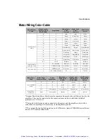
Page 84: ...wn M Z Black Yellow Black U Z Yellow Yellow Black Yellow E U White Brown Brown White Brown R U Brown White Brown White Brown White F V White Gray Orange White Gray S V Gray White Orange Black Gray White G W Red Orange Violet Red Orange H W Orange Red Violet White Orange Red K L 5VDC Red Blue Red Red Blue Jumper Installed CONS and TONS T 0V COMMON Blue Red Red White Blue Red D THERM Ground Green Re...

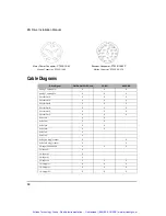
Page 85: ...n A X X Pulse In B X X Pulse In B X X Pulse In Z X Pulse In Z X Pulse In A single ended X X Pulse In B single ended X X I O Input Drive Enable X X X I O Input 1 X I O Input 2 X I O Input 3 X I O Input 4 X X X I O Output 1 X X X I O Output 2 X X X I O Output 3 X X X Motor Power Connector PT02E 16 8P Mating Connector PT06E 16 8S Encoder Connector PT02E 16 23P Mating Connector PT06E 16 23S Artisan Te...

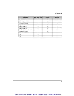
Page 86: ...d wire X Analog Out 0V X X X Analog Out Channel 1 X X X Analog Out Channel 2 X X X External Encoder 5 Power Out 200 ma X X External Encoder Common X X 15V Power Out 10 ma X RS 485 X RS 485 X Drive Signal CMDX CMDO ECI 44 CDRO AX4 CEN Artisan Technology Group Quality Instrumentation Guaranteed 888 88 SOURCE www artisantg com ...

Page 87: ... 3 INPUT I O 4 OUTPUT I O 3 OUTPUT I O 2 OUTPUT I O 1 24V I O 0V I O 24V I O 0V I O P1 MALE 44D P2 MALE 44D RED BLUE STRIPE BLUE RED STRIPE GRAY YELLOW STRIPE RED BROWN STRIPE BROWN RED STRIPE BLACK BLUE STRIPE BLUE BLACK STRIPE WHITE ORANGE STRIPE ORANGE WHITE STRIPE PURPLE BLUE STRIPE BLUE PURPLE STRIPE BLACK GREEN STRIPE GREEN BLACK STRIPE BLACK BROWN STRIPE BROWN BLACK STRIPE PURPLE ORANGE STR...

Page 88: ...T I O 2 INPUT I O 3 INPUT I O 4 OUTPUT I O 3 OUTPUT I O 2 OUTPUT I O 1 24V I O 0V I O 24V I O 0V I O RED BLUE STRIPE BLUE RED STRIPE GRAY YELLOW STRIPE RED BROWN STRIPE BROWN RED STRIPE BLACK BLUE STRIPE BLUE BLACK STRIPE WHITE ORANGE STRIPE ORANGE WHITE STRIPE PURPLE BLUE STRIPE BLUE PURPLE STRIPE BLACK GREEN STRIPE GREEN BLACK STRIPE BLACK BROWN STRIPE BROWN BLACK STRIPE PURPLE ORANGE STRIPE ORA...

Page 89: ...DER OUTPUT Z ENCODER OUTPUT Z I O SUPPLY DRIVE ENABLE INPUT ANALOG COMMAND INPUT ANALOG COMMAND INPUT DIAGNOSTIC OUTPUT COMMON OUTPUT 1 PULSE INPUT B PULSE INPUT B OUTPUT 2 OUTPUT 3 I O COMMON I O SUPPLY DIAGNOSTIC OUTPUT 1 DIAGNOSTIC OUTPUT 2 PULSE INPUT A PULSE INPUT A 40 25 44 42 43 41 15 30 11 12 14 13 29 28 26 27 39 38 37 36 35 34 33 32 31 17 21 8 9 10 7 23 24 22 3 5 6 4 19 20 18 1 2 16 WIRE ...

Page 90: ... OUTPUT A ENCODER OUTPUT A ENCODER OUTPUT B ENCODER OUTPUT B ENCODER OUTPUT Z 23 38 8 24 9 11 ENCODER OUTPUT Z N C GRN WHT WHT GRN YEL BRN BRN YEL BLK BRN BRN BLK GRY PUR PUR GRY YEL GRY N C N C GRY YEL RED WHT WHT RED BLU WHT WHT BLU BLK GRN GRN BLK BLU RED RED BLU N C N C N C N C OV I O SUPPLY COMMON 24V I O SUPPLY ANALOG INPUT 1 ANALOG INPUT 2 3 14 7 19 2 15 16 N C N C ANALOG COMMON ENABLE CONT...

Page 91: ...E NC NC NC NC NC NC SHELL MALE DB 9 CONN BRAID DRAIN 5 2 3 4 9 6 7 1 8 SHELL FEMALE DB 9 CONN 5 3 2 4 9 6 7 1 8 DDS DDS 5 4 9 5 2 3 4 9 7 1 6 8 5 2 3 4 9 7 1 6 8 FEMALE WHITE BLUE DB 9 DB 9 MALE DB 9 MALE SHELL P3 P2 P1 DRAIN WIRE BLACK GND 485 485 GND RX TX 485 485 Artisan Technology Group Quality Instrumentation Guaranteed 888 88 SOURCE www artisantg com ...

Page 92: ...F 78 R4 DB 9 FEMALE SHELL DB 9 MALE 7 8 1 6 9 4 R2 2 3 5 SHELL NOT USED NOT USED NOT USED 7 8 1 4 6 9 5V 485 485 T1 OUT TX R1 IN RX 3 2 5 GND 110 MAX 2 090 MIN 78 R 195 66 67 REF PIN 1 67 20 1 22 DB 9 MALE SHELL 7 8 1 6 9 4 2 3 5 DB 9 FEMALE SHELL 485 485 7 8 1 6 9 4 5V 3 2 5 GND NOT USED NOT USED NOT USED T1 OUT TX R1 IN RX R3 R2 R1 R4 Artisan Technology Group Quality Instrumentation Guaranteed 8...

Page 93: ...Cable 3 0 0 25 3 23 1 20 F C SOLDER SIDE E D BLK BLU A G H B SHELL C B GRN YEL BRN A D 3 0 0 25 3 99 1 40 C BLU SOLDER SIDE D E G F C B A SHELL GRN YEL BRN BLK A B D Artisan Technology Group Quality Instrumentation Guaranteed 888 88 SOURCE www artisantg com ...

Page 94: ...SHELL ORN BLU C B OVERALL TIN COPPER BRAID TWISTED PAIR 5 VDC 7 RED BLU NOT USED MOTOR OVERTEMP GND 23 N C 26 25 24 N C N C N C CASE BLU RED RED GRN GRN RED 18 N C 21 22 19 20 N C N C N C N C 16 8 17 9 N C A A Z Z B U W V W U V B GRN BRN WHT GRY BRN WHT RED ORN GRY WHT ORN RED WHT BRN 13 14 6 15 5 3 12 4 2 11 BLK YEL ORN 1 10 BLU PIN 1 P Y L W X J K H M N Z C T V G F U D E R A S B Artisan Technolo...

Page 95: ...21 18 16 17 LARGE 18 GA PAIR RED GRN OR 8 20 19 9 7 N C N C N C N C N C N C N C N C N C N C GRN RED RED GRN BLU RED RED BLU 14 13 12 11 10 6 5 3 4 2 1 RED ORN GRAY WHT WHT GRAY BRN WHT WHT BRN YEL BRN BLK GRN ORN BLU PIN 1 CONNECTOR SHELL OVERALL T C BRAID Artisan Technology Group Quality Instrumentation Guaranteed 888 88 SOURCE www artisantg com ...

Page 96: ...N C N C N C D W J X Y A V L T LARGE 18GA PAIR GRN WHT BRN GRY WHT ORN RED RED ORN BRN WHT WHT GRY BLK YEL BRN R F S H G P N M E U SHELL ORN BLU C B OVERALL TIN COPPER BRAID TWISTED PAIR P Y L W X J K H M N Z C T V G F U D E R A S B Artisan Technology Group Quality Instrumentation Guaranteed 888 88 SOURCE www artisantg com ...

Page 97: ...80 EN Drive Installation Manual Artisan Technology Group Quality Instrumentation Guaranteed 888 88 SOURCE www artisantg com ...

Page 98: ... do not affect each other any check box can be On or Off independently of all the others CRC Cyclical Redundancy Check Dialog Box A dialog box is a window that appears in order to collect information from the user When the user has filled in the necessary information the dialog box disappears DIN Rail Deutsche Industrie Norm Rail DLL In Microsoft Windows a Dynamic Link Library contains a library o...

Page 99: ...alog input the output tends to maintain it s current value until the input level changes past the point that set the current output value The difference in response of a system to an increasing input signal versus a decreasing input signal I O Input Output The reception and transmission of information between control devices In modern control systems I O has two distinct forms switches relays etc ...

Page 100: ...y number that is the most important or that has the most weight ms Millisecond NVM Non Volatile Memory NTC Negative Temperature Coefficient Resistor Option Button See Radio Button Opto isolated A method of sending a signal from one piece of equipment to another without the usual requirement of common ground potentials The signal is transmitted optically with a light source usually a Light Emitting...

Page 101: ... Modules Radio Button Also known as the Option Button In a dialog box radio buttons are small circles only one of which can be chosen at a time The chosen button is black and the others are white Choosing any button with the mouse causes all the other buttons in the set to be cleared RAM RAM is an acronym for Random Access Memory which is a memory device whereby any location in memory can be found...

Page 102: ...he transfer of a complete set of parameters from PowerTools or an FM P VAC Volts Alternating Current VDC Volts Direct Current Windows Microsoft Microsoft Windows is an operating system that provides a graphical user interface extended memory and multi tasking The screen is divided into windows and the user uses a mouse to start programs and make menu choices Artisan Technology Group Quality Instru...

Page 103: ...86 Epsilon Eb and EN Drives Reference Manual Artisan Technology Group Quality Instrumentation Guaranteed 888 88 SOURCE www artisantg com ...

Page 104: ...g 24 D DDS XXX Cable 74 Declaration of Conformity viii Diagnostic Analog Output Test Points 40 Diagnostic Cable DGNE Diagram 41 Diagnostic Display 35 Diagnostics and Troubleshooting 35 Drive and Motor Combination Specifications 50 Drive Enable Wiring 22 Drive Faults 42 Drive Mounting 9 Drive overload protection vii Drive Specifications 47 E Electrical Installation 10 Electromagnetic Compatibility ...

Page 105: ...mmunications 33 N NT Motor Dimensions 62 NTE M 207and 212 Brake Motors 64 NTE M 320 330 345 and 355 Motors 66 NTE 207 and 212 Motors 62 NTM 207 and 212 Motors 63 P Power Dissipation 53 Power Dissipation Calculation 54 Pulse Mode Wiring 29 R Rebooting the Drive 42 Resetting Faults 42 S Safety Considerations xi Safety of Machinery xi Safety Precautions xi Serial Communications 32 Setup Commissioning...

Page 106: ...r Contact Information 79 View Motor Parameters 44 Viewing Active Drive Faults 42 W Watch Window 42 Wire Size 15 Wiring Notes 9 Artisan Technology Group Quality Instrumentation Guaranteed 888 88 SOURCE www artisantg com ...

Page 107: ...90 Epsilon Eb and EN Drives Reference Manual Artisan Technology Group Quality Instrumentation Guaranteed 888 88 SOURCE www artisantg com ...

Page 108: ...Artisan Technology Group Quality Instrumentation Guaranteed 888 88 SOURCE www artisantg com ...

Page 109: ...sy products and services call 800 397 3786 or contact our website at www emersonct com Control Techniques Drives Inc Division of EMERSON Co 12005 Technology Drive Eden Prairie Minnesota 55344 U S A Customer Service Phone 952 995 8000 or 800 397 3786 Fax 952 995 8129 Technical Support Phone 952 995 8033 or 800 397 3786 Fax 952 9995 8020 Printed in U S A Artisan Technology Group Quality Instrumentat...

Page 110: ...quipment Have surplus equipment taking up shelf space We ll give it a new home Learn more Visit us at artisantg com for more info on price quotes drivers technical specifications manuals and documentation Artisan Scientific Corporation dba Artisan Technology Group is not an affiliate representative or authorized distributor for any manufacturer listed herein We re here to make your life easier How...

Reviews: