2
To Contact Avocent Technical Support: Visit www.avocent.com
590-1279-501B
Emerson, Emerson Network Power and the Emerson Network Power logo are trademarks or service marks of Emerson Electric Co. Avocent, the Avocent logo and LongView are trademarks or service marks of
Avocent Corporation. All other marks are the property of their respective owners. This document may contain confidential and/or proprietary information of Avocent Corporation, and its receipt or possession does
not convey any right to reproduce, disclose its contents, or to manufacture or sell anything that it may describe. Reproduction, disclosure, or use without specific authorization from Avocent Corporation is strictly
prohibited. ©
2016
Avocent Corporation. All rights reserved.
Avocent
®
LongView
TM
3000 Series
High Performance KVM Extender System
Quick Installation Guide
also provide Video Compensation Mode
for configuration of cable types and
lengths, video gains and color skew. Three
equalization bands within the remote
extenders ensure that a sharp video image
is received every time.
Cable Extension Rules
Use the following table to determine the
appropriate cable type to support the
distance of your configuration.
MAXIMUM CABLE LENGTH
CAT 5 / CAT 5e
250 m
CAT 6 / CAT 7
300 m
CAT 7a Patch
200 m
Installation
Instructions apply for both modules unless
referenced specifically.
NOTE:
Prior to the following steps, ensure
your computer is turned off.
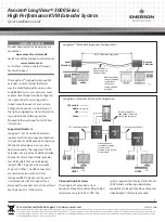
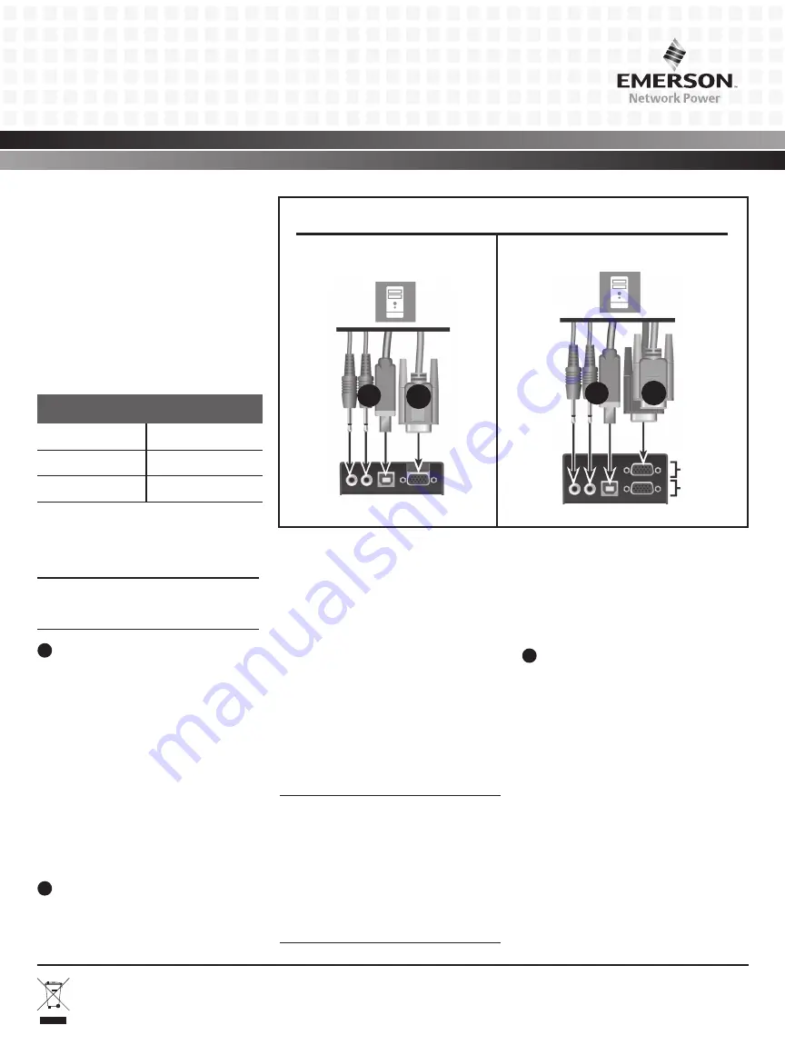
1
Connecting local extender video
For the LongView 3010 extender, connect
a video cable from the computer to the
video port on the left end of the extender.
For the LongView 3020 extender, connect
the video cable from the primary video
port on the computer to the bottom
(primary) video port on the left end of the
extender. Then, connect the cable from the
secondary video port on the computer to
the top (secondary) video port on the left
end of the extender.
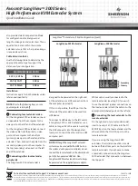
2
Connecting other local extender
peripherals
The LongView 3010 local extender is
designed to be powered on the right end
of the extender via a USB connection from
the computer (see step 5).
If this is not possible, the USB port on the
left end of the extender can be used for a
USB device.
To connect a USB device to the left end of
a LongView 3010 or 3020 extender, use a
cable no longer than three meters and plug
the USB connector into the designated
local port. Connect the other end to a USB
computer port.
NOTE: Although the LongView™ extender
system may be used with other USB hubs in
the system, due to power constraints, do not
connect the local extender to the downstream
port of a bus-powered USB hub. Also,
LongView 3020 local extenders must always
be powered via the supplied power adaptor.
While audio is usually connected to the
remote extender (see step 9), if you wish
to use the optional speaker connections on
the local extender, attach the cables to the
appropriately labeled ports on the left end.
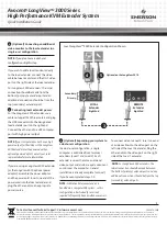
3
Connecting the local extender to the
remote extender
On the right end of your extender model,
insert one end of a CAT cable into the TO
REMOTE port on the local extender and the
other end into the TO LOCAL port on the
remote extender.
If you are using the LongView 3020
extenders, the initial connection is made
between the bottom ports on the local and
remote extenders. If you choose to make
a secondary connection on the LongView
3020 extender, that connection is between
the top ports.
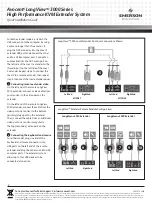
LongView
TM
Extender Left End Configuration (Local)
Secondary
Primary
LongView
TM
3010 Extender
LongView
TM
3020 Extender
1
1
2
2

