


39
Series 7400 Single Phase 1+N UPS
1
7
1
7
1
7
1
7
1
7
1
7
1
7
1
7
M2
M3
M4
M5
1
2
3
SH1
CN1
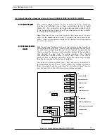
A S 4 0 0 I N T E R F A C E B O A R D
P a r t N o . 1 0 0 2 0 1 1 2 0 0 0 4
2
3
4
5
Synchro
off
Inverter
off
TB - M1
Control Inputs
R L 7
R L 9
R L 6
R L 8
RL10
1
Common
2
3
4
5
6
7
Mains or Rectifier
Failure
UPS On
Low Battery
Load on Mains
Load on Maintenance
Bypass
Load on Inverter
R L 2
R L 4
R L 1
R L 3
R L 5
1
Common
2
3
4
5
6
7
Mains or Rectifier
Failure
UPS On
Low Battery
Load on Mains
Load on Maintenance
Bypass
Load on Inverter
Outputs from M2 - M5 to
Remote Alarm or AS400
Figure 22: Four output AS400 Interface Board


