Flange Size and Rating
MAX PRESSURE
PSIA (kPaA)
Burn Time
Lowest
MESG
Gas Group
Direction of Flow
Serial Number
BI-DIRECTIONAL
Date of Manufacture
Customer Tag Number
WARNING: THIS DEVICE MUST BE PERIODICALLY
SERVICED FOR CONTINUED SAFE OPERATION
EU-Type Examination Certificate
NoBo No.
EN No.
ISO 16852
FLAME ARRESTORS HAVE INSTALLATION AND APPLICATION LIMITS.
TYPE DESIGNATION IN ACCORDANCE WITH ISO 16852.
FLAME ARRESTORS HAVE INSTALLATION AND APPLICATION LIMITS.
TYPE DESIGNATION IN ACCORDANCE WITH ISO 16852.
3
Model 2400
North America
Only
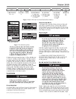
Figure 2
. Model 2400 In-line Duct Flame Arrestor Model Number
2400
/
IIA
- IL
-
C
4
-
A
-
046
CONNECTION SIZE
IEC
GAS GROUP
IN-LINE
SERIES
HOUSING MATERIAL
CELL MATERIAL
HOLE PATTERN
CRIMP
DESIGNATION
2400 = 24 in.
IIA
C = Carbon steel
4 = 304 Stainless steel
6 = 316 Stainless steel
H = Hastelloy
®
4 = 304 Stainless steel
6 = 316 Stainless steel
H = Hastelloy
®
A = ASME CL150
B = DIN PN10
C = DIN PN6
D = Standard
E = Other
046
059
into the unprotected side of the flame arrestor
assembly in order that the flow of explosive
vapors be stopped within t
bt
/2 (4 minutes) in
the event of an elevated temperature relative
to normal operating conditions. Bypassing,
sufficient diluting or inerting are measures
equivalent to stopping the flow.
Stabilized burning is steady burning of a flame stabilized at,
or close to, the flame arrestor element. This flame arrestor
has been tested for the time it takes for a stabilized flame,
at greatest heat saturation conditions, to heat the arrestor
element above the auto-ignition temperature of the process
gas stream resulting in flame propagation through the
arrestor. The short time burn rating is shown on the product
warning plate. Stabilized burning after ignition creates
additional hazards in applications where there could be
a continuous flow of the flammable mixture towards the
unprotected side of the flame arrestor.
Installation
!
WARNING
Always ensure that the system is at
atmospheric pressure and there is no ignitable
gas that could flash when installing this unit.
Flow Direction
The Model 2400 In-line Duct Flame Arrestor is bi-directional,
however, the temperature sensor must be located on the
unprotected (hot) side of the arrestor.
Hastelloy
®
is a mark owned by Haynes International, Inc.
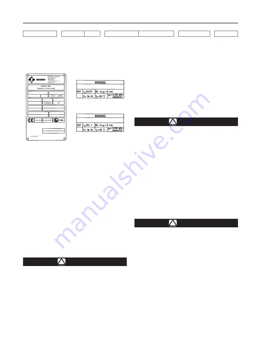
Figure 3
. Product Marking Plates
Example Nameplate
Example Warning Plate 059 Option
Example Warning Plate 046 Option
Pipe Connections
The Model 2400 In-line Duct Flame Arrestor is fitted with
plate flanges with ANSI, DIN or custom bolting patterns
which require the use of full faced gaskets. Do not use ring
gaskets for the installation since excessive distortion of the
plate flanges can occur.
Pipe Length
!
WARNING
Do not exceed the maximum L/D pipe length
rating (L
u
) of the flame arrestor. If flame
propagation occurs at a distance greater
than the L/D rating of the flame arrestor,
the flamer arrestor could be ineffective in
stopping the flame propagation.
Extended lengths of pipe allow the flame to advance into
more severe states of flame propagation including high
pressure deflagrations or detonations. All Flame Arrestors
included in this series should be installed in accordance with
Table 1.
L
u
, expressed as a multiple of pipe diameters, is the
allowable length of pipe between the flame arrestor and
the ignition source without bends or other turbulence
causing devices.
Bends and/or Flow Obstructions
!
WARNING
No instrument, tubing or other device
whatsoever shall circumvent the flame
arrestor in such a manner to allow a flame
path to exist around the flame element
of the arrestor. When instrumentation is
installed in such a manner that it creates a
path circumventing the flame element of an
arrestor, measures must be taken to prevent
passage of flame through the instrumentation
device and/or system. Instrumentation must
be capable of withstanding the maximum
and minimum pressures and temperatures to
which the device may be exposed.
Bends in piping, pipe expansions, and/or contractions,
valves, orifice plates or flow obstructing devices of any kind
contribute to turbulent flow. Turbulent flow enhances mixing
of the combustible gases, greatly increasing the combustion
intensity. This can result in increased flame speeds, higher

