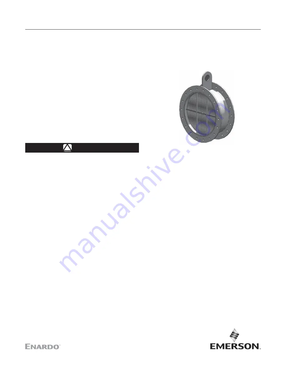
Model 2400
June 2019
Instruction Manual
D104470X012
Model 2400 In-line Duct Flame Arrestor
North America
Only
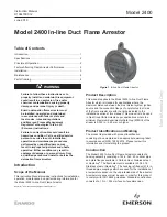
Figure 1
. In-line Duct Flame Arrestor
Table of Contents
Introduction ............................................................................1
Specifications ........................................................................2
Principle of Operation ............................................................2
Factors Affecting Flame Arrestor Performance ......................2
Installation .............................................................................3
Maintenance ..........................................................................4
Parts Ordering .......................................................................4
!
WARNING
Failure to follow these instructions or to
properly install and maintain this equipment
could result in an explosion, fire and/or
chemical contamination causing property
damage and personal injury or death.
Enardo detonation flame arrestor must
be installed, operated and maintained
in accordance with federal, state and
local codes, rules and regulations
and Emerson Process Management
Regulator Technologies Tulsa, LLC
(Emerson) instructions.
Failure to correct trouble could result in a
hazardous condition. Call a qualified service
person to service the unit. Installation,
operation and maintenance procedures
performed by unqualified person may
result in improper adjustment and unsafe
operation. Either condition may result in
equipment damage or personal injury. Only
a qualified person must install or service the
detonation flame arrestor.
Product Description
This manual applies to the Model 2400 In-line Duct Flame
Arrestor which is intended for applications where the
maximum distance between the most distant system ignition
source and the connection flange of unprotected (hot) side
of the flame arrestor are with the limits indicated in the
installation section of this manual. This product is to be used
in Gas Group IIA flammable vapor applications where the
minimum Maximum Experimental Safe Gap (MESG) of the
stream is 0.035 in. / 0.90 mm or higher.
Product Identification and Marking
The product is provided with product identification
consisting of a nameplate and an appropriate warning label
in accordance with ISO 16852:2016. Please review this
information prior to installing the product.
Construction
The Model 2400 In-line Duct Flame Arrestor consists of a
housing assembly consisting of 24 in. Sch. 40 nominal pipe
and plate flanges available in Carbon steel, Stainless steel
or Hastelloy
®
. The flame element is available in 304, 316
Stainless steel or Hastelloy
®
. The housing is fitted with 1/2 in.
threaded pipe couplings which are used for the installation of
a temperature sensor on the unprotected side of the arrestor.
A temperature sensor must be used in order for this product
to comply with ISO 16852 guidelines. Standard construction
consists of a 10 in. / 254 mm face-to-face dimension.
Introduction
Scope of the Manual
This Instruction Manual provides instructions for installation,
operation, maintenance and parts ordering information for
the Model 2400 In-line Duct Flame Arrestor.
Hastelloy
®
is a mark owned by Haynes International, Inc.

