EME Controller OE5JFL May 2009
Page 6 of 13
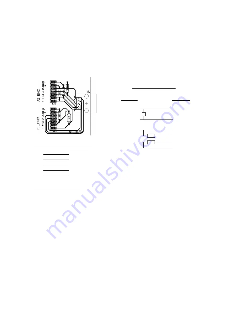
A LAN cable is used to connect the encoders. With another jumper
you can select the DC for the encoders between 5V or 12V.
At the other end of the LAN cable, there is a small splitter PCB
for encoder connections.
MAB25 /ETS25 connection
Splitter Encoder
+5V VDD
2(6) CS
0(4) CLK
1(5) DATA
GND GND
(no resistors needed!)
A2-S-S connection
Splitter Encoder
0(4) 6: DATA- (blue)
270R
1(5) 5: DATA+ (yellow)
+12V 4: +DC (white)
2k2 3: BUSY- (brown)
2k2 2: BUSY+ (green)
GND 1: GND (red)
At the splitter the pin numbers 0,1,2
for Az and 4,5,6 (in brackets) for El
are connected via the LAN cable and
the switching transistors to
P1.0,..,P1.6 of the 20pin connector.


