background image

Tasks to install a DAE5S

EMC VNXe — Installing an Optional 25-Slot Disk-Array Storage System (DAE5S)

7

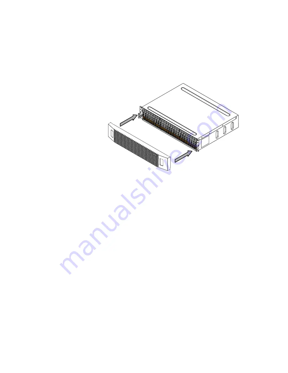
Task 6: Install the DAE5S bezel

Install the DAE5S front bezel:

1. Align the bezel with the DAE5S.

2. Gently push the bezel into plan on the cabinet until it latches

3. Secure the bezel by turn the key in the lock.

CL4588

Summary of Contents for DAE5S

Page 1: ...ersonal injury and or damage to the equipment do not attempt to lift and install the enclosure into a rack without a mechanical lift and or help from another person Tasks to install a DAE5S Task 1 Ver...

Page 2: ...Verify that you received the following Component Quantity Disk array enclosure DAE5S Rear view Front view 1 DAE5S rail kit 1 includes 2 rails and 16 screws Power cords 2 Bezel for disk array enclosure...

Page 3: ...e disk array enclosure Install the DAE5S rails in the next available 2U space directly above the base system DPE or the last DAE5S in system Most cabinets mark 1U 1 7 inch increments with horizontal l...

Page 4: ...ure Task 4 Install the disk array enclosure in the cabinet rack The enclosure is heavy and should be installed into a rack by two people To avoid personal injury and or damage to the equipment do not...

Page 5: ...re Note If the chassis does not slide all the way into the cabinet you may need to further loosen the screws that hold the rear of the rails in place then adjust the rails to allow the tabs to fit int...

Page 6: ...mpting to use the new disks in your system Avoid touching any exposed electronic components and circuits on the disk Do not stack disks upon one another or place them on hard surfaces When installing...

Page 7: ...25 Slot Disk Array Storage System DAE5S 7 Task 6 Install the DAE5S bezel Install the DAE5S front bezel 1 Align the bezel with the DAE5S 2 Gently push the bezel into plan on the cabinet until it latch...

Page 8: ...separate AC power circuit a Attach the B left module to the circuit shared with DPE power supply B b Attach the A right module to the circuit shared with DPE power supply A 2 Attach the retention bai...

Page 9: ...storage system connect the DAE to the DPE IMPORTANT Connecting a DAE to expansion port 1 on the DPE is not supported a If you are connecting to a VNXe3100 DPE that has a cover on expansion port 0 on S...

Page 10: ...e new DAE5S to the expansion port on LCC B of the DAE below 3 Verify that the bus loop ID LED displays the expected value Note Each LCC includes a bus loop identification LED indicator This indicator...

Page 11: ...ware revisions Copyright 2012 EMC Corporation All rights reserved Published in the USA Published August 2012 EMC believes the information in this publication is accurate as of its publication date The...

Reviews: