background image

P5    OPERATION

4. OPERATION 

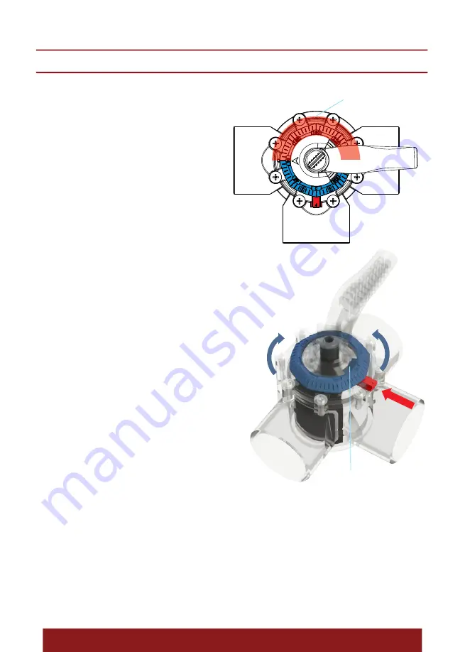
4.1 INLET CHANGING

User  can  set  either  port  as  an  inlet  port.  The 

arrow  on  the  handle  indicates  the  diverter 

position  and  the  port  flow  is  blocked  when 

the arrow on the handle is pointing at it. The 

new  dial  has  markings  from  0  to  360  degree 

where 270 to 90 degree range does not allow 

the  arrow  to  turn  to.  As  a  result,  the  diverter 

is limited to turn to the range 90 to 270 only.

Allowed area for the Arrow turning.

Fig. 5

1.  Turn  the  knob  approrimately  half  turn 

counter clockwise to loosen the handle. 

2. Push and hold the Lock Nut to release the 

lock of the Dial and then turn the Dial “0” to 

the  port  which  is  defined  as  an  inlet  (port 

where water enters). 

3.  Lock  the  Dial  by  releasing  the  push,  the 

Dial  will  be  locked  when  the  Lock  Nut  pops 

out (if the Lock Nut does not pops out, which 

means the Lock Nut is not pointing to either 

marking (0, 90, 180, 270) on the Dial.

4. Turn the knob clockwise until the handle is 

tightened to fix the setting. 

Follow the following procedure to change the inlet.  

Turn the handle:

Before turning the handle, you must loosen the knob. Otherwise, the handle is locked.

1. Power off the pumps. Make sure that water in the valley is not flowing.

2. Turn the knob at least two turns counter clockwise to loosen the handle.

3. Turn the handle, the arrow on the handle indicates the diverter position. 

4. The 270 to 90 degree range which is marked on the dial does not allow the arrow to turn to.

5. Turn the knob clockwise until the handle is tightened to fix the setting.

Stopper

Fig. 6

Summary of Contents for 91600005

Page 1: ...USER MANUAL FLEX DIVERTER VALVE Installation and Operation manual EMVA22101140 Model FLEX Series...

Page 2: ...4 5 5 6 7 8 FLEX DIVERTER VALVE INSTALLATION AND OPERATION MANUAL P1 CONTENT 1 PRODUCT INTRODUCTION 2 SPECIFICATIONS 3 INSTALLATION 3 1 PLUMBING 3 2 FUNCTION AND APPLICATIONS 4 OPERATION 4 1 INLET CHA...

Page 3: ...ction A in B in C in D in E in Description 91600106 FLEX40 3 A PVC CPVC 1 2 2 36 1 89 7 3 6 6 5 87 ID 1 pipe slip in OD 2 coupler 91600108 FLEX50 3 A PVC CPVC 2 2 2 95 2 36 7 3 6 6 5 87 ID 2 pipe slip...

Page 4: ...aterial Connection A in B in C in D in E in Description 91600006 FLEX40 2 A PVC CPVC 1 2 2 36 1 8 7 3 6 6 4 3 ID 1 pipe slip in OD 2 coupler 91600008 FLEX50 2 A PVC CPVC 2 2 2 95 2 36 7 3 6 6 4 3 ID 2...

Page 5: ...sure that no glue enters the main valve body Fig 4 3 2 FUNCTION AND APPLICATIONS Function Application Knob To lock handle and the Dial Loosen knob to adjust handle and dial Lock Nut To lock the Dial A...

Page 6: ...where water enters 3 Lock the Dial by releasing the push the Dial will be locked when the Lock Nut pops out if the Lock Nut does not pops out which means the Lock Nut is not pointing to either markin...

Page 7: ...rt 2 Port 3 C Port 1 Port 2 Port 3 D Port 1 Port 2 Port 3 P6 DIAL DIRECTION Dial direction A Standard B C D Port where water enters Inlet Port 2 3 1 2 3 1 Port Where Water Exits Port that the Diverter...

Page 8: ...is not available as a separate part If you need to replace the valve housing you must replace the entire valve 4 3 1 2 7 8 9 P7 SPARE PART LIST 5 6 Key No Part No Description Qty 1 570349858 Knob 1 2...

Page 9: ...ty extends only to products purchased from Emaux authorized reseller This Limited Warranty does not extend to any product that has been damaged or rendered defective a as a result of accident misuse o...

Page 10: ...YOUR PREMIER SUPPLIER EMAUX WATER TECHNOLOGY CO LTD www emauxgroup com...

Reviews: