background image


Copy right © 2018 Shenzhen Emakefun Technology co., Ltd.


22 


We can see that motor 1 and motor 2 are constantly turning and reversing. 

Stepper Motor 

Principle of stepper motor 


Stepper motor is an open-loop control motor that converts electrical pulse signals into angular displacement 

or line displacement. It is the main actuator in modern digital program control systems and widely used. In 

the case of non-overloading, the speed and stop position of the motor only depends on the frequency of the 

pulse signal and the number of pulses. 


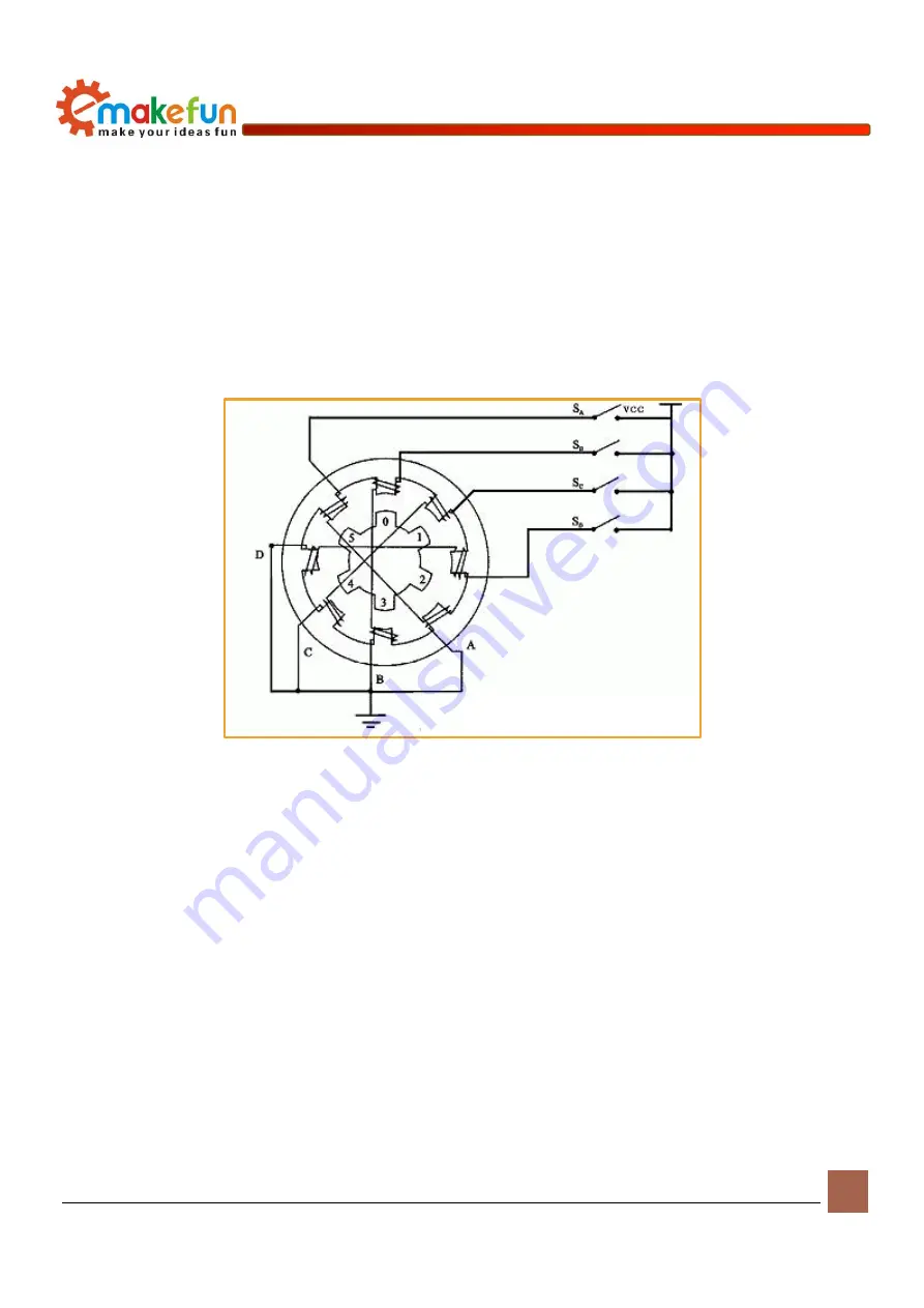
Figure 7-1 stepper motor schematic


As shown in Figure 7-1 above, there are multiple pairs of magnetic poles inside the stepping motor.If the 

power-on state remains unchanged, the stepper motor will remain in a fixed state. Only by changing the 

energization state of each pair of poles can the stepper motor continue to rotate. Therefore, the stepper motor 

cannot be directly connected to the DC or AC power supply, and a dedicated driving power supply (stepper 

motor driver) must be used. The controller (pulse signal generator) can control the angular displacement by 

controlling the number of pulses to achieve the purpose of accurate positioning. At the same time, the speed 

and acceleration of the motor rotation can be controlled by controlling the pulse frequency, thereby 

achieving the purpose of speed regulation. 

Driving stepper motor 

Connect a stepper motor to port 1 and port 2 of the stepper motor as shown in Figure 6-5. The working 

voltage of the stepper motor is between 5~12V. If the working voltage of the stepper motor is too low or too 

high, there is a phenomenon that the burned motor or the drive board collapses, and the battery should be 

Summary of Contents for PS2X

Page 1: ...Copy right 2018 Shenzhen Emakefun Technology co Ltd 1 PS2X Motor Drive Board Instruction Manual V 1 2...

Page 2: ...Technology co Ltd 2 Revision Date Version Description Author 2018 11 27 V 1 0 Create Abbott Chen 2019 1 2 V 1 1 Rearrange the document frame and fix the error Ken chen 2019 1 11 V 1 2 Optimize and sup...

Page 3: ...Power Supply 17 DC Motor 18 Motor control principle 18 Stepper Motor 22 Encode Motor 23 RGB LED light 26 RGB WS2812 Introduction 26 Working principle of WS2812 RGB LED Light 27 WS2812 RGB LED Light D...

Page 4: ...Shenzhen Emakefun Technology co Ltd 4 PS2 Remote Control 40 PS2 Introduction 40 Drive PS2 remote 42 NRF2401 44 NRF24L01 module Introduction 44 Drive NRF24L01 module 44 Appendix 46 External sensor conn...

Page 5: ...board is specially designed for the Arduino uno R3 motherboard It can be directly plugged into the Arduino Uno The motherboard integrates a passive buzzer 2 RGB LED lights and 1 infrared receiver It...

Page 6: ...d data sheet used on the driver board Schematic means the schematic used by the driver board Scratch means the image library and scratch user manual and sample program PS2X Motor Driver Board Composit...

Page 7: ...nd the current is 500mA 2A Or PH2 0 wiring port power supply the voltage range is 6 12V there is a power supply jumper cap on the drive board you need to short circuit the IN and 5V Q How many motors...

Page 8: ...the relevant tutorial under this link https github com keywish motor drive board Q Where can we download the program examples A Download the relevant tutorial under this link https github com keywish...

Page 9: ...nager to view the port com lpt If there is no com or lpt or if there is only an unknown device there is a problem with the controller board or USB cable 2 Right click on My Computer and select Device...

Page 10: ...Copy right 2018 Shenzhen Emakefun Technology co Ltd 10 Driver Software option Figure 4 3 Update Driver...

Page 11: ...co Ltd 11 2 Nextly next select the Browse my computer for driver software option Figure 4 4 Driver update selection interface 3 Finally select the driver file named FTDI USB Drivers located in the Dri...

Page 12: ...Copy right 2018 Shenzhen Emakefun Technology co Ltd 12 Figure 4 5 Select drive path Figure 4 6 install driver...

Page 13: ...ically notifying you that the drive is successful Figure4 7 Driver installation completed At this time we return to the Device Manager interface the computer has successfully identified the Arduino as...

Page 14: ...d as COM15 but different computers may be different You may be COM4 COM5 etc but the Arduino Uno must be the same If you do not find the USB serial port it may be that you installed it incorrectly or...

Page 15: ...wn programs these are compiled and can be used normally which is very helpful for beginners The Preference option is mainly the setting of parameters such as language font etc Figure 4 11 File menu ba...

Page 16: ...nology co Ltd 16 USB serial port is mainly selected as shown in Figure 4 13 If you are not sure you can view it in the Device Manager and select the corresponding COM port Figure 4 12 Tools interface...

Page 17: ...board connected to the PS2X Motor Driver Board to the computer via a USB cable 2 Click Connect Serial port COM4 the number of this COM port is different for different computers 3 Burning sample progr...

Page 18: ...al oscillator or can also not be connected to external crystal oscillator up to 50MHz Supporting 2 3V 5 5V voltage maximum withstand voltage is 5 5V With power on reset software reset and other functi...

Page 19: ...ntrol output terminals STBY is normal working standby state control pin VM 4 5 15 V and VCC 2 7 to 5 5 V are the motor drive voltage input and the logic level input respectively In the Arduino the ana...

Page 20: ...amely DC motor interface 1 DC motor interface 2 DC motor interface 3 and DC motor interface 4 which can be directly connected to the drive via the terminals Connect 4 DC motors to DC motor interface 1...

Page 21: ...Shenzhen Emakefun Technology co Ltd 21 Figure 6 3 DC Motor connection diagram Figure 6 4 Motor drive schematic Experimental procedure Open the IDE load the file AdvancedExperiment TB6612_DC_Motor TB66...

Page 22: ...fixed state Only by changing the energization state of each pair of poles can the stepper motor continue to rotate Therefore the stepper motor cannot be directly connected to the DC or AC power suppl...

Page 23: ...An encoder is a rotary sensor that converts angular or angular velocity into a series of electrical digital pulses We can measure the displacement or velocity information through the encoder The enco...

Page 24: ...square wave signal of the AB phase output and the method of use is the same The following is a simple schematic diagram Figure 8 1 Schematic diagram of the Coded Motor Encoder wiring instructions Spec...

Page 25: ...e of the encoder motor is between 5 and 12V After connecting the motor to the line find the encoded motor test sample program in the sample program sample program file path load file AdvancedExperimen...

Page 26: ...me in order to reduce the power supply ripple the three channels have a certain delay turn on function which can reduce the circuit ripple installation more easily during frame refresh Unlike the trad...

Page 27: ...ng data is shaped and amplified by the internal shaping processing circuit and then the output is forwarded to the next cascaded pixel through the DO port and the signal is reduced by 24 bits after ea...

Page 28: ...e above 50 s during reset T0H 0 yards high voltage time 0 5 s T1H 1 yard high voltage time 2 s T0L 0 yards low voltage time 2 s T1L 1 yard low voltage time 0 5 s RES Reset code low voltage time 50 s F...

Page 29: ...es active buzzer and passive buzzer The main difference between the two is as follows The ideal signal for active buzzer operation is direct current usually labeled VDC VDD and so on Because the buzze...

Page 30: ...he audio signal is T 1 587 1703 5775us and the half cycle time is 852us The device count 852us 1us 852 the I O port is inverted at 852 every count the middle adjustment Re of C major is obtained In ad...

Page 31: ...cteristics steering gear are small volume large torque high stability simple external mechanical design Either in hardware or software design the design of steering engine is an important part of car...

Page 32: ...ade reduction gear so that the voltage difference is 0 and the motor stops rotating When the control circuit board receives the control signal from the signal line the motor is controlled to rotate th...

Page 33: ...ction and size to produce the motor s rotation signal Figure 11 3 Relationship between servo output angle and input pulse Drive Servo The PS2X Motor Driver Board driver board can drive the servo the s...

Page 34: ...4 Note The sample program file path is controlled by the I O digital pin If you need to control the servo through I2C you need to connect the wiring of the servo to the corresponding interface in the...

Page 35: ...the steering gear will be driven obviously the speed of the steering gear will be much faster and the force during rotation will be very high strong and accurate The specific steps are as follows 1 S...

Page 36: ...signal transmission pin A1 the ultrasonic signal receiving pin A1 and the ground GND The four pins are connected to the corresponding pins of the ultrasonic module as shown in Figure 12 1 as shown in...

Page 37: ...nfrared receiving head Mini ultra thin infrared remote control has 17 function keys the transmission distance can reach 8 meters which is very suitable for Control a variety of equipment indoors Figur...

Page 38: ...evel regardless of the distance between the infrared transmitter and the receiver The AC signal enters the bandpass filter The bandpass filter can pass the load wave of 30KHZ to 60KHZ enter the compar...

Page 39: ...rared signal Of course you can also write a program that uses infrared remote control to control the rotation of the motor or the rotation of the servo It is more intuitive to see the effect of the in...

Page 40: ...ion PS2 Remote Control PS2 Introduction The PS2 handle is the remote control handle of Sony game machine Sony series game host is in the world very popular The outstanding characteristic is that this...

Page 41: ...he handle on the open off off the handle switch to on In the case of no search to the receiver the lamp on the handle flashing constantly in a certain period of time has not been found in the receiver...

Page 42: ...the host This signal changes to low in the last cycle of each 8 bit data sending and the CS remains low If the CS signal do not remain low the PS host will try another device in about 60 microseconds...

Page 43: ...e board you will see the print content on the serial monitor Of course you can also write a program that uses PS2 to control the rotation of the motor or the rotation of the servo It is more intuitive...

Page 44: ...has four operating modes transceiver mode configuration mode idle mode and shutdown mode Drive NRF24L01 module Insert the nRF24L01 module into the corresponding interface on the PS2X Motor Driver Boar...

Page 45: ...Copy right 2018 Shenzhen Emakefun Technology co Ltd 45 Figure 16 2 Connection diagram of Nrf24l01 Figure 16 3 Schematic diagram of the Nrf24l01 connection...

Page 46: ...Board also reserves 10 sets of expansion pin interfaces of which 6 are general digital I 0 interfaces and 4 are I2C control interfaces These expansion interfaces can be used for external connection of...

Reviews: