background image

16

Capítulo 4 : Mandos e instrumentos de control

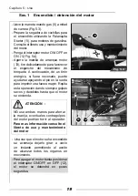
Sec.1    Descripción de los mandos

9


8


10


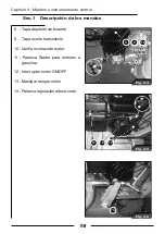
Fig. 4.4

11


12


13


Fig. 4.5

14


Fig. 4.6

8    -  Tapa depósito carburante 

9    -  Tapa aceite transmisión 

10  -  Varilla nivel aceite motor

11 - Palanca Starter para motores a 

gasolina

12 -  Interruptor motor ON/OFF 

13 - Manija arranque motor

14 - Palanca regulación alteza corte

Summary of Contents for Efco DR 55 H 6,5

Page 1: ...eft muß das Gerät während seiner gesamten Lebensdauer begleiten WARNING This owner s manual must stay with the machine for all its life ATENCION Este manual debe acompañar a la máquina durante toda su vida útil UWAGA Niniejsza instrukcja powinna towarzyszyc urzadzeniu przez caly okres jego eksploatacji DR55H6 5 WB55H6 5 NTS 50 68240078B Ott 2010 Member of the YAMA group 42011 Bagnolo in Piano RE I...

Page 2: ......

Page 3: ...1 1 USO E MANUTENZIONE I ...

Page 4: ...cniche 13 Sez 1 Pesi e misure d ingombro 13 Sez 2 Motore e Informazioni generali 14 Capitolo 4 Comandi e strumenti di controllo 15 Sez 1 Descrizione dei comandi 15 Sez 2 Leve regolazioni in altezza e laterale del manubrio 17 Capitolo 5 Utilizzazione 18 Sez 1 Avviamento arresto motore 18 Sez 2 Leva frizione avanzamento macchina e movimento lame 20 Sez 3 Leva selettore marce e Leve sbloccaggio ruote...

Page 5: ...ole diversità delle condizioni d impiego è impossibile alla società fornire pubblicazioni perfet tamente aggiornate e complete rela tive alle prestazioni o ai metodi d uso delle macchine di sua fabbricazione e quindi assumersi responsabilità per perdite o danni che possano derivare da quanto pubblicato o da qualsiasi errore od omissione Nel caso in cui il mezzo debba essere usato in condi zioni an...

Page 6: ...oso e più cauto nel maneggia re macchinari e attrezzature agricole Leggere e seguire attentamente le istruzioni di sicurezza riportate in det taglio in questo capitolo del manuale Se non indicato diversamente i dati e le informazioni contenuti in questo ma nuale sono applicabili a tutti i modelli Il contenuto di questo manuale è con forme alle ultime informazioni tecniche disponibili al momento de...

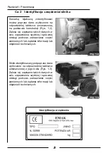
Page 7: ...efficiente quando si ordinano parti di ricambio o quando si richiedono in formazioni o delucidazioni tecniche Il motore viene identificato attraverso i dati impressi nell apposita targhetta di identificazione posta sulla parte latera le del motore stesso Fig 1 3 E importante segnare tali dati allo scopo di assicurare un servizio pronto ed efficiente quando si ordinano parti di ricambio o quando si...

Page 8: ...rsone addette all uso e alla manutenzione del motocoltivatore L installazione eseguita correttamente associata ad una regolare manutenzio ne è utile per prevenire guasti Se tut tavia si dovessero verificare problemi di funzionamento durante il periodo di validità della garanzia si raccomanda di osservare la seguente procedura informate immediatamente il Riven ditore da cui è stato acquistato il mo...

Page 9: ...ettini di Assistenza possiedono tutti i Manuali d Officina e tutte le altre informazioni tecniche necessarie a ga Capitolo 1 Premessa Sez 3 Garanzia NOTA Il montaggio di parti non originali può portare all utilizzo di un ricam bio di qualità inferiore Il Costruttore della falciatrice a flagelli non si as sume nessuna responsabilità per qualsiasi perdita o danno derivante dall installazione di tali...

Page 10: ...rtimento che incontrerete in questo libretto sono di tre tipi ATTENZIONE Questo simbolo di allarme identifica importanti avvertenze di sicurezza sulla falciatrice a flagelli o segnala zioni di sicurezza sul libretto o altro ve Quando vedete questo simbolo state molto attenti perchè esiste il pericolo di infortuni gravi o mortali Seguite le istruzioni indicate nell av vertenza di sicurezza NOTA E u...

Page 11: ... in sicurezza Prestare attenzione agli altri È VOSTRA responsabilità leggere e comprendere questo manuale e il libretto delle Norme generali di sicurezza allegato prima di utilizzare la falciatrice a flagelli Dovrete seguire queste norme di sicurezza che vi accompagneranno durante la vostra giornata di lavoro Ricordatevi sempre che VOI siete i soli responsabili della vostra sicurezza Buone norme d...

Page 12: ... biarne o alterarne lo stato di allerta ed il coordinamento Un operatore in prescrizione o sotto controllo per uso di sostanze stupefacenti neces sita di un autorizzazione medica per certificare se è in grado di utilizzare la falciatrice a flagelli in sicurezza Capitolo 2 Norme generali e dispositivi di sicurezza Sez 2 Precauzioni per lavorare in sicurezza Proteggete voi stessi Indossate tutti gli...

Page 13: ...dBA si raccomanda di utilizzare adeguati mezzi di protezione individuale dell udito Rilevamenti del mezzo Rilevamenti secondo i seguenti studi sule Norme Armonizzate EN 12733 Pressione acustica 92 dBA Potenza acustica 106 dBA Vibrazioni 9 3 m s2 VALORI MASSIMI RILEVATI NELLA GAMMA DEI MOTORI DISPONIBILI Capitolo 2 Norme generali e dispositivi di sicurezza Sez 2 Precauzioni per lavorare in sicurezz...

Page 14: ...OTORE ACCESO DI BLOCCARE LE LEVE FRIZIONE AVANZAMENTO MAC CHINA E MOVIMENTO LAME PER POTER OPERARE SULL ATTREZ ZO ESISTE IL PERICOLO DI IN FORTUNI GRAVI O MORTALI La Leva frizione rotore lame va sem pre azionata con due mani Sgancia te l attacco di sicurezza della Leva frizione rotore lame come illustrato Fig 2 4 Non operate su terreni con una pen denza laterale superiore al 15 Ridurre la velocità...

Page 15: ...13 Versione TS 50 Peso 125 Kg Dimensioni Capitolo 3 Dati e caratteristiche tecniche Sez 1 Pesi e misure d ingombro 1640 968 1115 658 543 577 667 548 50 ...

Page 16: ...ione meccanica Cambio 1 marcia avanti Velocità 2 1 Km h Larghezza di taglio 50 cm Gruppo di taglio Rotore con 26 flagelli Sterzo Frizioni di sterzo indipendenti sulle ruote motrici Freno di servizio e stazionamento A inserimento automatico al disinnesto della frizione Pneumatici Posteriori 4 00 4 tractor Capitolo 3 Dati e caratteristiche tecniche Sez 2 Motore e Informazioni generali Fig 3 1 Fig 3 ...

Page 17: ...di qui elencati occorre leggere attentamente il capitolo 5 Utilizzazione 1 Leva sbloccaggio ruota sinistra 2 Leva frizione avanzamento mac china 3 Leva sbloccaggio ruota destra 4 Manettino comando gas 5 Leva innesto rotore 6 Attacco di sicurezza innesto rotore 7 Leva regolazione in altezza late rale del manubrio Capitolo 4 Comandi e strumenti di controllo Sez 1 Descrizione dei comandi 1 2 Fig 4 1 ...

Page 18: ...i comandi 9 8 10 Fig 4 4 11 12 13 Fig 4 5 14 Fig 4 6 8 Tappo serbatoio carburante 9 Tappo olio trasmissione 10 Asta livello olio motore 11 Levetta Starter per motori a benzina 12 Interruttore motore ON OF 13 Maniglia avviamento motore 14 Leva regolazione altezza taglio ...

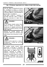
Page 19: ...ego lazione laterale del manubrio per po ter operare vicino a fossati e sponde Il manubrio può assumere più posizioni a destra e sinistra Per muovere il manubrio lateralmente svitate la leva Fig 4 8 successiva mente spostate il manubrio o a destra o a sinistra Per ribloccare il manubrio riavvitate la leva verificando che la base delle stegole sia inserita correttamente Fig 4 7 Fig 4 8 ATTENZIONE S...

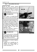
Page 20: ... bene che l olio sia al massimo per avere una lubrificazione sicura ed ottimale In caso di rabocco utilizzate solo olio ESSO UNIFARM 15 40 W Per ulteriori informazioni consultate il libretto d istruzioni del motore Prima di avviare la falciatrice a flagelli assicuratevi che Verificate per la vostra sicurezza che le leve avanzamento macchina e in nesto rotore lame siano in posizione verticale Fig 5...

Page 21: ...perazione dando sempre colpi secchi e decisi sino all accensione del motore Unavoltacheilmotoreèavviatoèconsi gliabilelasciarlogirareavuotoperqual che istante permettendo all olio di rag giungere tutti gli organi in movimento Per spegnere il motore basta po sizionare l interruttore ON OFF su OFF 12 il motore si fermerà in po chi istanti 5 Fig 5 3 ATTENZIONE NON usate entrambe le mani per afferrare...

Page 22: ... la leva che viene bloccata da un attacco di sicurezza Fig 5 8 Questo attacco pensato per la vostra sicurezza impe disce che l operatore possa inserire il rotore lame mentre la falciatrice a fla gelliè in movimento ma solo a mezzo fermo Fig 5 5 1 2 Fig 5 8 attiva il rotore porta lame E necessa rio utilizzare due mani per sganciare la leva che viene bloccata da un attacco di sicurezza Fig 5 8 Quest...

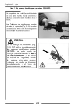
Page 23: ...vanzamento Capitolo 5 Utilizzazione Sez 3 Leve sbloccaggio ruote DX SX Fig 5 10 25 Fig 5 11 ATTENZIONE Se si lavora in pendenza Fig 5 11 NON utilizzate simultaneamente le Leve sbloccaggio ruote DX SX così facendo viene automaticamente escluso il freno di stazionamento ed annulata quindi la sua funzione di sicurezza Rilasciate la Leva frizione avanzamento macchina le ruote si bloccano immediatament...

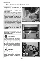
Page 24: ...one del volume dell erba da tagliare Fig 5 12 Fig 5 14 Se l altezza di taglio è regolata troppo bassa potrebbero verificarsi i seguenti effetti negativi proiezione verso l esterno di oggetti estranei come pietre ecc accumoli di terra e fango all interno del carter protezione rotore Di con seguenza lo scarico dell erba non può avvenire regolarmente veloce usura delle lame e possibilità che queste s...

Page 25: ...gasolio ed alcool non è approvata data l eventuale lubrifi cazione insufficiente del sistema di iniezione combustibile ATTENZIONE Pulite la zona del tappo d introdu zione e tenetela pulita Riempite il serbatoio alla fine di ogni giornata in modo da ridurre la condensa not turna DIVIETO Con il motore in moto non togliete mai il tappo ne fate rifornimento Mentre si riempie il serbatoio man tenete il...

Page 26: ...essa cosa vale per la Leva frizione innesto rotore lame quando il rullo porta lame impie ga molto tempo per fermarsi bisogna come per la Leva frizione agire sui registri posizionati sulle rispettive leve comando Fig 6 3 Per le Leve sbloccaggio ruote e la Leva selettore marce Fig 6 4 bisogna comportarsi allo stesso modo quando si avverte troppo gioco alle leve veri ficate che fra l estremità superi...

Page 27: ...1 1 UTILISATION ET ENTRETIEN F ...

Page 28: ...et encombrement 13 Section 2 Moteur et informations générales 14 Chapitre 4 Commandes et instruments de contrôle 15 Section 1 Description des commandes 15 Section 2 Leviers de réglage en hauteur et réglage latéral du guidon 17 Chapitre 5 Utilisation 18 Section 1 Mise en marche arrêt du moteu 18 Section 2 Levier d embrayage de l avancement de la machine et du mouvement des couteaux 20 Section 3 Lev...

Page 29: ...re de les monter et de les utiliser Le montage de pièces de rechange de qualité inférieure peut provoquer des dommages importants Nous recommandons donc à la clientèle d acheter les pièces nécessaires exclusivement chez un vendeur autorisé Les conditions d emploi de cette machine sont extrêmement variées par conséquent il est impossible pour le fabricant de fournir des publications parfaitement à ...

Page 30: ...ement l usager avait été moins pressé et plus prudent dans le maniement des machines et des outillages agricoles Lire et suivre attentivement les consignes de sécurité détaillées figurant au chapitre dédié du manuel A moins qu il n en soit indiqué autrement les données et les informations contenues dans ce manuel sont applicables à tous les modèles Le contenu de ce manuel est conforme aux dernière...

Page 31: ...er un service prompt et efficace lorsque vous commanderez des pièces détachées ou que vous demanderez des renseignements ou des éclaircissements techniques Le moteur est identifié au moyen de données gravées dans la plaquette d identification spéciale placée sur la partie latérale du moteur même Fig 1 3 Veuillezprendrenotedecesdonnées en vue de vous assurer un service prompt et efficace lorsqu vou...

Page 32: ...on et l entretien de la machine même concernant les instruments et les commandes de contrôle l entretien périodique et les mesures de précaution relativement à la sécurité Ce cours d instructions doit impliquer tous les usagers et les personnes préposées à l entretien du motoculteur Afin de prévenir tout dommage une installation correctement exécutée accompagnée d un entretien régulier s avère uti...

Page 33: ... Durant la période de validité de la garantie il est recommandé de faire effectuer toutes les opérations d entretien et de réparation par votre Revendeur qui sera ainsi à même d exercer un contrôle attentif du bon fonctionnement et des performances de votre nouvelle tondobroyeuse à fléaux Afin de tirer le meilleur parti de votre tondobroyeuse à fléaux il est impératif de ne pas suspendre les contr...

Page 34: ...ts de la tondobroyeuse à fléaux La sécurité de l usager constitue l un des principaux soucis de tous ceux qui conçoivent et développent une nouvelle tondobroyeuse à fléaux les concepteurs cherchent à prévoir le plus grand nombre possible de dispositifs de sécurité Malgré cela chaque année bien des accidents se produisent qui auraient pu être évités si seulement l usager avait été moins pressé et p...

Page 35: ... parties relativement à Précautions à prendre pour travailler en sécurité Contrôle des équipements Entretien de la machine Travailler en sécurité Veiller à faire attention aux autres Il est de VOTRE responsabilité de lire et bien comprendre ce manuel ainsi que la notice portant sur les Règles générales de sécurité en annexe avant d utiliser la tondobroyeuse à fléaux Vous devrez suivre ces consigne...

Page 36: ... portée votre surface de travail Evitez autant que possible de travailler avec la tondobroyeuse à fléaux près de fossés d excavations ou de trous Ralentissez lorsque vous braquez vous passez sur une pente ou que vous traversez des terrains escarpés glissants ou boueux Eloignez vous des terrains à trop forte pente afin d agir en toute sécurité Regardez bien où vous allez surtout au bout du champ su...

Page 37: ...supérieur à 85 dB A le port de protections auditives individuelles adaptées est recommandé Relèvements effectués sur la machine Ci après les relèvements effectués suivant les études portant sur les Normes Harmonisées EN 12733 Pression acoustique 92 dBA Puissance acoustique 106 dBA Vibrations 9 3 m s2 VALEURS MAXIMALES RELEVEES DANS LA GAMME DE MOTEURS DISPONIBLES Chapitre 2 Normes générales et dis...

Page 38: ...oteur éteint afin d éviter la survenue d incidents ou d accidents graves NE TENTEZ JAMAIS MOTEUR ALLUME DE BLOQUER LES LEVIERS D EMBRAYAGE D AVANCEMENT DE LA MACHINE ET DE MOUVEMENT DES LAMES POUR POUVOIR TRAVAILLER SUR VOTRE MACHINE LE RISQUE D ACCIDENTS GRAVES OU MORTELS N EST PAS A ECARTER Fig 2 3 Fig 2 4 Pendant l utilisation du hachesarments assurez vous que personne ne se trouve en l espace ...

Page 39: ...13 Version TS 50 Poids 125 Kg Dimensions 1640 968 1115 658 543 577 667 548 50 Chapitre 3 Données et caractéristiques techniques Section 1 Poids et encombrement ...

Page 40: ... 205 cc Puissance 4 8 kW 6 5 cv Pour d autres informations consulter la notice d instructions du moteur Transmission mécanique Boîte de vitesse 1 marche avant Vitesse 2 1 Km h Largeur de coupe 50 cm Groupe de coupe Rotor à 26 Àéaux Direction Embrayages de direction indépendants sur les roues motrices Frein de service et stationnement A insertion automatique au moment du débrayage Pneus Arrière 4 0...

Page 41: ...ici lire attentivement le chapitre 5 Utilisation 1 Levier de déblocage roue gauche 2 Levier d embrayage avancement machine 3 Levier de déblocage roue droite 4 Manette des gaz 5 Levier d embrayage du rotor 6 Dispositif de sécurité de l embrayage du rotor 7 Levier de réglage en hauteur et réglage latéral du guidon Chapitre 4 Commandes et instruments de contrôle Section 1 Description des commandes 1 ...

Page 42: ...andes 9 8 10 Fig 4 4 11 12 13 Fig 4 5 14 Fig 4 6 8 Bouchon du réservoir de carburant 9 Bouchon de l huile de la transmission 10 Jauge de l huile du moteur 11 Starter pour moteurs à essence 12 Interrupteur moteur ON OFF 13 Démarreur moteur 14 Levier de réglage de la hauteur de coupe ...

Page 43: ...e de régler latéralement le guidon pour pouvoir travailler près des fossés et des berges ATTENTION Faites très attention aux talus terre pleins et berges de fleuve de consistance meuble Le guidon peut prendre plusieurs positions à droite et à gauche Pour bouger le guidon latéralement dévisser le levier Fig 4 8 puis déplacer le guidon ou à droite ou à gauche Pour le rebloquer revisser le levier en ...

Page 44: ...souhaitable de compléter le niveau d huile jusqu au repère maximum afin d assurer une lubrification optimale En cas de remplissage à ras bord n utilisez que de l huile ESSO UNIFARM 15 40 W Pour de plus amples renseignements veuillez consulter le manuel d instructions du Moteur Pour votre sécurité avant de faire démarrer la tondeuse à Àéaux véri ez que les leviers d avancement de la machine et d em...

Page 45: ... opération en donnant toujours des coups secs et décidés jusqu à l allumage du moteur 5 Fig 5 3 ATTENTION NE PAS utiliser les deux mains pour saisir la poignée car des contrecoups éventuels du moteur pourraient blesser l opérateur Pour d autres informations consulter la notice d utilisation et d entretien du moteur 11 12 13 Fig 5 4 Chapitre 5 Utilisation Section 1 Mise en route arrêt du moteur Une...

Page 46: ... relâchez le levier et votre engin s arrêtera immédiatement ATTENTION Quand le rotor à couteaux est en fonction assurez vous toujours qu il n y a personne à proximité Fig 5 9 N ESSAYEZ JAMAIS DE FAIRE LE MOINDRE REGLAGE QUAND LE MOTEUR EST ALLUME Le levier d embrayage du rotor à couteaux met en mouvement le rotor en question Il est nécessaire de se servir de ses deux mains pour débloquer le levier...

Page 47: ...ilisation Section 3 Leviers de déblocage des roues droite gauche Fig 5 10 25 Fig 5 11 ATTENTION Si vous travaillez en pente Fig 5 11 N UTILISEZ PAS simultanément les leviers de déblocage des roues droite gauche car cela exclut automatiquement le frein de stationnement qui est un important dispositif de sécurité Relâchez donc le levier d embrayage avancement machine les roues se bloqueront immédiat...

Page 48: ...r du carter de protection du rotor empêchant l évacuation régulière de l herbe cela peut déterminer une usure rapide et la possibilité de rupture des couteaux La protection avant Fig 5 14 s ovre ou se ferme en fonction du volume d herbe à couper Fig 5 12 Fig 5 14 INTERDIT Vous NE DEVEZ JAMAIS utiliser la machine en laissant la protection ouverte car cela pourrait provoquer la projection d objets L...

Page 49: ...ool car il peut provoquer une mauvaise lubri cation du système d injection du combustible ATTENTION Nettoyez la zone du bouchon de remplissage et faites en sorte qu elle reste propre Remplissez le réservoir à la n de chaque journée de façon à réduire la condensation nocturne INTERDIT N enlevez jamais le bouchon et ne mettez jamais de carburant quand le moteur est en marche Pendant que le réservoir...

Page 50: ...evier a besoin d un réglage De même pour le levier d embrayage du rotor à couteaux quand celui ci est lent à s arrêter il faut comme pour le levier d embrayage de l avancement agir sur les dispositifs de réglage placés sur les leviers de commande respectifs Fig 6 3 Pour les leviers de déblocage des roues et le levier sélecteur de vitesses Fig 6 4 agir de la même façon si vous remarquez qu il y a t...

Page 51: ...1 1 BEDIENUNG UND WARTUNG D ...

Page 52: ...en 13 Abschn 1 Gewicht und Gesamtabmessungen 13 Abschn 2 Motor und allgemeine Informationen 14 Kapitel 4 Steuer und Kontrollgeräte 15 Abschn 1 Beschreibung der Steuerungen 15 Abschn 2 Hebel für das seitliche Verstellen und die Höhenverstellung des Lenkers 17 Kapitel 5 Gebrauch 18 Abschn 1 Anlassen Abstellen des Motors 18 Abschn 2 Kupplungshebel für den Maschinenvorlauf und die Messerbewegung 20 Ab...

Page 53: ...satzbedingungen ist es der Gesellschaft nicht möglich perfekt aktualisierte Handbücher bereitzustellen die eine Beschreibung aller Leistungen oder Gebrauchsweisen der von ihr gefertigten Maschinen enthält und die Gesellschaft kann keine Haftung für Ausfälle oder Schäden übernehmen die auf diese Veröffentlichung oder auf Fehler oder Auslassungen zurückzuführen sind Wenn das Gerät unter besonders sc...

Page 54: ...chtigerundweniger überstürztvorgegangenwäre Dieindiesem Kapitel des Handbuchs aufgeführten Sicherheitsvorschriften und anweisungen aufmerksam lesen und befolgen Wenn nicht anders angegeben sind die in diesem Handbuch enthaltenen Informationen und Daten für alle Modelle anwendbar Der Inhalt dieses Handbuchs entspricht den zum Zeitpunkt der Drucklegung aktuellen technischen Informationen Der Herstel...

Page 55: ...estellung von Ersatzteilen oder bei der Anforderung von Informationen oder technischen Erläuterungen zu gewährleisten Der Motor wird mittels der in das entsprechende Kennschild gestanzten Daten identifiziert Dieses Kennschild ist der Motorseite angebracht Abb 1 3 Es ist wichtig diese Daten zu vermerken um einen schnellen und effizienten Service bei der Bestellung von Ersatzteilen oder bei der Anfo...

Page 56: ...uftragten Personen teilnehmen Die korrekt durchgeführte Montage ist gemeinsam mit einer regelmäßigen Wartung nützlich zum Vorbeugen gegen Störungen Falls es während des Gültigkeitszeitraums der Garantie zu Betriebsstörungen kommen sollte ist wie nachfolgend beschrieben vorzugehen Informieren Sie umgehend den Vertragshändler bei dem die Landmaschine gekauft wurde und geben Sie das Modell und die Se...

Page 57: ...ber alle Werkstatthandbücher und alle weiteren technischen Informationen die erforderlichsind umdenhohenStandard Kapitel 1 Vorwort Abschn 3 Garantie ANMERKUNG Die Montage von Nichtoriginaler satzteilen kann dazu führen dass ein Ersatzteil schlechterer Qualität verwendet wird Der Hersteller des Schlegelmähers haftet nicht für Ver dienstausfälle oder Schäden die auf eine Montage solcher minder werti...

Page 58: ...inweise sind in drei Typen unterteilt Diese Maschine wurde für den Gebrauch durch einen einzigen Bediener zum Mähen Schneiden und oder Häckseln von hohem Gras Hecken und Gestrüpp entwickelt Jeder andere Gebrauch ist als unsachgemäß anzusehen Der Bediener hat dafür zu sorgen dass andere Personen während des Betriebs der Maschine einen Mindestabstand von 10 Metern zu derselben einhalten Die in diese...

Page 59: ...f andere Personen SIEsinddafürverantwortlich diesesHandbuchunddasdemselbenbeigestellte HeftmitdenAllgemeinenSicherheitsvorschriftenzulesenundzuverstehen bevor Sie den Schlegelmäher das erste Mal benutzen Sie müssen diese Sicherheitsvorschriften die Sie während Ihres Arbeitstags begleiten werden genau befolgen Denken Sie immer daran dass SIE alleine für Ihre Sicherheit verantwortlich sind Das Beach...

Page 60: ...2 Vorsichtsmaßnahmen für eine sichere Arbeit für Ihren Schlegelmäher vorgesehen sind Schützen Sie sich selbst Tragen Sie Schutzkleidung Abb 2 1 und die Ihnen für Ihre Arbeit zur Verfügung gestellten PSA Gehen Sie kein Risiko ein Sie benötigen folgende Schutzkleidung Einen Schutzhelm Schutzbrille oder Schutzmaske Gehörschutz Atemschutzmaske oder filter Schlechtwetterkleidung Reflektierende Kleidung...

Page 61: ...llten geeignete persönliche Gehörschutzausrüstungen angewandt werden Messungen am Fahrzeug Messungen gemäß der folgenden Harmonisierten Normen EN 12733 Schalldruckpegel 92 dBA Schallleistung 106 dBA Vibrationen 9 3 m s2 AN DEN VERFÜGBAREN MOTOREN GEMESSENE HÖCHSTWERTE Kapitel 2 Allgemeine Sicherheitsvorschriften und vorrichtungen Abschn 2 Vorsichtsmaßnahmen für eine sichere Arbeit Abb 2 2 ACHTUNG ...

Page 62: ...randere Gegenstände in Richtung Bediener oder sich in der Nähe aufhaltender Personen geschleudert werden Beim stationären Gebrauch des Schlegelmähers ist die Gangschaltung immer in den Leerlauf zu schalten und die Räder der Landmaschine und der Ausrüstung sind mit Holzkeilen abzusichern Der Messerrotorkupplungshebel muss Abb 2 3 Abb 2 4 aufhalten Beim Gebrauch des Mulchers sicherstellen dass sich ...

Page 63: ...13 Ausführung TS 50 Gewicht 125 Kg Abmessungen 1640 968 1115 658 543 577 667 548 50 Kapitel 3 Technische Daten und Eigenschaften Abschn 1 Gewicht und Gesamtabmessungen ...

Page 64: ... Leistung 4 8 kW 6 5 cv Für weitere Informationen schlagen SiebittedieGebrauchsanweisungen des Motors nach Mechanisches Getriebe Schaltung 1 Vorwärtsgänge Geschwindigkeit 2 1 Km h Schnittbreite 50 cm Schnittaggregat Rotor mit 26 Schlegeln Lenkung Lenkungskupplungen unabhängig von den Antriebsrädern Betriebs und Standbremsen Automatische Betätigung beim Auskuppeln der Kupplung Reifen Hinten 4 00 4 ...

Page 65: ...uch der SteuerelementeistKapitel5 Gebrauch aufmerksam zu lesen 1 Entriegelungshebel linkes Rad 2 Kupplungshebel für Maschinenvorlauf 3 Entriegelungshebel rechtes Rad 4 Gashebel 5 Rotorkupplungshebel 6 Sicherheitsanschluss Rotorkupplung 7 Verstellhebel Lenkradhöhe und seitliche Verstellung Kapitel 4 Steuer und Kontrollgeräte Abschn 1 Beschreibung der Steuerungen 1 2 Fig 4 1 3 5 4 6 Fig 4 2 7 Fig 4 ...

Page 66: ...Beschreibung der Steuerungen 9 8 10 Fig 4 4 11 12 13 Fig 4 5 14 Fig 4 6 8 Kraftstofftank 9 Getriebeölstopfen 10 Motorölstab 11 Starterhebel für Benzinmotoren 12 Motorschalter ON OF 13 Schnitthöheneinstellhebel 14 Hebel für Regulierung der Schnitthöhe ...

Page 67: ...er Lenker kann in mehrere Stellungen nach rechts und links verstellt werden Zum seitlichen Verstellen des Lenkers den Hebel Abb 4 8 lockern und den Lenker darauf entweder nach rechts oder nach links verstellen Den Lenker wieder festspannen indem der Hebel wieder festgeschraubt wird Sicherstellen dass die Lenkholmsockel korrekt eingesetzt sind Fig 4 7 Fig 4 8 Fig 4 9 ACHTUNG Wenn man mehrere Stunde...

Page 68: ... um eine sichere und optimale Schmierung zu gewährleisten Zum Nachfüllen von Motoröl ist ausschließlich das Öl ESSO UNIFARM 15 40 W zu verwenden Für weitere Informationen ist die Gebrauchsanweisung des Motors nachzuschlagen Vor dem Anlassen des Schlegelmähers ist Folgendes durchzuführen oder sicherzustellen Überprüfen Sie zu Ihrer Sicherheit dass die Maschinenvorlaufhebel und der Messerrotorkupplu...

Page 69: ...ang so lange wiederholen bis der Motor anläuft Nach dem Anlassen des Motors sollte dieser kurz im Leerlauf laufen damit das Öl alle sich bewegenden Teile der Maschine erreichen kann Zum Abstellen des Motors wird der ON OFF Schalter auf OFF gestellt 12 Der Motor wird nach einigen Augenblicken angehalten 5 Fig 5 3 11 12 13 Fig 5 4 Kapitel 5 Gebrauch Abschn 1 Anlassen Abstellen des Motors Zum Abstell...

Page 70: ...üssen beide Hände verwendet werden Dieser für Ihre Sicherheit entwickelte Anschlussverhindert dassderBediener den Messerrotor einschaltet während der Schlegelmäher in Bewegung ist Folglich kann der Messerrotor nur bei stillstehender Maschine eingeschaltet werden Fig 5 5 1 2 Fig 5 8 Zum Lösen des durch einen Sicherheitsanschluss Abb 5 8 blockierten Hebels müssen beide Hände verwendet werden Fig 5 9...

Page 71: ...mähers Kapitel 5 Gebrauch Abschn 3 Entriegelungshebel Räder rechts links Fig 5 10 25 Fig 5 11 ACHTUNG Bei der Arbeit an Hängen Abb 5 12 die beiden Radentriegelungshebel Rechts Links NICHT gleichzeitig verwenden da in diesem Fall automatisch die Standbremse und folglich deren Sicherheitsfunktion ausgeschlossen werden Den Maschinenvorlaufkupplungshebel loslassen die Räder werden umgehend angehalten ...

Page 72: ...utz Abb 5 14 öffnet oder schließt sich in Abhängigkeit von der zu schneidenden Grasmenge Wenn eine zu niedrige Schnitthöhe eingestellt wird kann es zu folgenden negativen Auswirkungen kommen Schleudern von Fremdkörpern wie Steine usw nach außen Ansammlung von Erde und Schlamm im Rotorschutzgehäuse Dadurch kann das einwandfreie Austreten des Grases beeinträchtigt werden Schneller Verschleiß der Mes...

Page 73: ...G Das Gemisch aus Gasöl undAlkohol ist nicht zugelassen da es eventuell zu einer ungenügenden Schmierung der Kraftstoffeinspritzanlage kommt ACHTUNG Den Bereich um den Befüllstopfen reinigen und sauber halten Den Tank bei Arbeitsende immer befüllen damit sich in der Nacht kein Kondenswasser bildet VERBOT Bei laufendem Motor niemals den Stopfen öffnen und keinen Kraftstoff einfüllen Beim Befüllen d...

Page 74: ...plungshebel wenn die Messerträgerrolle zu langsam angehalten wird Wie beim KupplungshebelistindiesemFallaufdie an den entsprechenden Steuerhebeln angebrachten Einstellvorrichtungen einzuwirken Abb 6 3 Bei den Radentriegelungshebeln und den Gangschalthebeln Abb 6 4 ist auf die gleiche Weise vorzugehen wenn ein zu großes Spiel der Hebel festgestellt wird Das Spiel wird kontrolliert indem geprüft wir...

Page 75: ...1 1 USE AND MAINTENANCE GB ...

Page 76: ...a and characteristics 13 Section 1 Weights and sizes 13 Section 2 Engine 14 Section 3 General information 14 Chapter 4 Control commands and instruments 15 Section 1 Description of controls 15 Section 2 Height and side handlebar control levers 17 Chapter 5 Use 18 Section 1 Start stop engine 18 Section 2 Clutch levers vehicle and blades 20 Section 3 Gear lever and wheel unlock levers 21 Section 4 Cu...

Page 77: ...rking conditions Therefore we cannot assume responsibility for leaks or damage as could derive from following up any published article or error or omission In case the machine has to be used under particularly heavy abnormal conditions for example high groundwater or muddy terrain we adviseyoutoconsultyourDealerinorder to obtain specific instruction in order not to invalidate the guarantee The bui...

Page 78: ...y the safety instructions as offered in detail in this chapter of the manual All data and information in this manual are applicable to all models unless indicated otherwise The contents of this manual are conform the latest available technical informationatthemomentitwasissued The Building Company reserves the right to carry out modifications to the machine at any moment without warning or incurri...

Page 79: ...for a quick and efficient service when spare parts need to be ordered or when requesting information or technical clarifications The identification of the engine with the data pounded on the appropriate identification label on the side of the engine Fig 1 3 It is important to write down those data for a quick and efficient service when spare parts need to be ordered or when requesting information ...

Page 80: ...or all people using the machine or doing maintenance work to it Once the installation has been done correctly aregularmaintenanceroutine is useful to prevent faults However should functional problems occur during the guarantee cover period we suggest the following procedure inform the Dealer where you bought the walking tractor immediately mentioning Model and Serial Number It is important not to ...

Page 81: ...ment They receive regularly Assistance Journals have all the Garage Manuals and all other technical information necessary in order to guarantee a high standard of assistance for the repairs Chapter 1 Introduction Section 3 Guarantee WARNING The assembly of non original parts may result in a lesser working quality of the spare part The Builder of the flail mower will not assume any responsibility f...

Page 82: ...and underbush to be used by one operator only Any other improper use is forbidden The operator is responsible to keep a distance of at least ten meters from the machine clear of any people when using the machine Please read and follow the safety instructions in this chapter of the manual in detail CAUTION This alarm symbol identifies important safety warnings for the flail mower or safety signals ...

Page 83: ...oklet contains Precautions for safety at work Check the equipment Maintenance of the machine Safety at work Pay attention to others It is YOUR responsibility to read and understand the manual and the booklet with the General safety regulations as attached to the flail mower before using it You should follow these safety regulations as they will guide you through your work day Please always remembe...

Page 84: ...ot take alcohol or medication that could change or alter his alertness or his coordination An operator who is under prescription of medication will need a medical authorization to certify that he is ready to use the flail mower safely Chapter 2 General safety measures and regulations Section 2 Precautions for safety at work Protect yourself When at work wear all protective gear Fig 2 2 and necessa...

Page 85: ...superior to 85 dBA we advise the use of appropriate means of individual ear protection Surveys of the machine Surveys according to the following Harmonized Norms EN studies 12733 Acoustic pressure 92 dBA Acoustic power 106 dBA Vibrations 9 3 m s2 MAXIMUM VALUES DETECTED IN THE RANGE OF AVAILABLE ENGINES Chapter 2 General safety measures and regulations Section 2 Precautions for safety at work Fig ...

Page 86: ...even serious nature WHENADJUSTINGTHEMACHINE DO NEVER TRY TO BLOK THE CLUTCH LEVERS OF THE VEHICLE AND THE MOVEMENT OF THE BLADES WHILE THE ENGINE IS GOING THERE IS THE DANGER OF SERIOUS ACCIDENTS OR DEATH The blade rotor clutch Lever has to be operated with two hands Undo the safety lock of the blade rotor clutch Lever as illustrated Fig 2 5 Do not work on a slope with a lateral inclination of mor...

Page 87: ...13 Version TS 50 Weight 125 Kg Sizes 1640 968 1115 658 543 577 667 548 50 Chapter 3 Technical data and characteristics Section 1 Weights and sizes ...

Page 88: ...pacity 205 cc Power 4 8 KW 6 5 cv For further information please consult the instruction booklet of the Engine Mechanical gear box Gear 1 gears forward Speed 2 1 Km h Mowing width 50 cm Cutting group Rotor with 26 flails Steering Independent steering clutches on the engine wheels Break and service break Service Automatically insertible when releasing the clutch Tires Rear 16x6 50 8 tractor ...

Page 89: ...ase read carefully Chapter 5 Use for the correct use of the commands as indicated below 1 Unlock left wheel 2 Clutch lever vehicle 3 Unlock right wheel 4 Gas command stick 5 Rotor control 6 Safety lock rotor 7 Handlebar side height adjustment lever Chapter 4 Control commands and instruments Section 1 Description of the commands 1 2 Fig 4 1 3 5 4 6 Fig 4 2 7 Fig 4 3 ...

Page 90: ...nts Section 1 Description of the commands 9 8 10 Fig 4 4 11 12 13 Fig 4 5 14 Fig 4 6 8 Fuel tank cap 9 Gear oil cap 10 Engine oil level bar 11 Start lever for gasoline engines 12 Engine ON OFF 13 Engine starting handle 14 Cutting height control ...

Page 91: ...en you work close to ditches or banks The handlebar can take different positions on the right and left To move the handlebar sideways unscrew the lever Fig 4 8 then move the handlebar either to the right or to the left To re lock the handlebar screw the lever back on checking that the base of the handlebar is correctly inserted Fig 4 7 Fig 4 8 Fig 4 9 CAUTION When working several hours at a time r...

Page 92: ...ximum level in order to warrant a correct and optimal lubrification When topping up oil only use ESSO UNIFARM 15 40 W oil For further information please consult the instruction booklet of the engine Before starting the flail mower make sure you Check for your safety that the machine groundspeed and blade rotor engagement levers are in the vertical position Fig 5 1 1 2 Fig 5 1 9 8 10 Fig 5 2 STOP N...

Page 93: ...ation always giving short sharp tugs until the engine ignites Once the engine has started it is advisable to leave it idling for a few moments to allow the oil to reach all the moving parts To turn off the engine just put the ON OFF switch onto OFF 12 the engine will stop in a few moments 5 Fig 5 3 11 12 13 Fig 5 4 Chapter 5 Use Section 1 Start stop engine To turn off the engine just put the ON OF...

Page 94: ...o hands to unhook the lever that is locked by a safety catch Fig 5 8 This catch designed for your safety prevents the operator from being able to engage the blade rotor while the flail mower is moving but only when the machine is stationary Fig 5 5 1 2 Fig 5 8 It is necessary to use two hands to unhook the lever that is locked by a safety catch Fig 5 8 Fig 5 9 CAUTION In case of difficulty release...

Page 95: ...nge direction when in movement Chapter 5 Use Sect 3 RH LH wheel release levers Fig 5 10 25 Fig 5 11 CAUTION When working on a slope Fig 5 11 do NOT use the right and left wheel unlockers simultaneously this would exclude the service brake and overturn its security function Release the vehicle clutch Lever and the wheels block immediately and the service break will reactivate ...

Page 96: ...y guard As a result the grass cannot get unloaded regularly fast wear of the blades and risk of them breaking The front guard Fig 5 14 opens or closes depending on the volume of grass to cut Fig 5 12 Fig 5 14 Fig 5 15 STOP You should NEVER use the machine with the protection cover left open This could cause projection of objects The protection can be fixed in the open position only during the subs...

Page 97: ...ION Mixing diesel and alcohol is not allowed given the possibly insufficient lubrification of the fuel injection system CAUTION Clean around the tank cap and keep this area clean Fill the tank at the end of every working day so that nightly condense is reduced DIVIETO Do never open the cap or fill up when the engine is going While the tank is filling up keep holding control of the filling pistol C...

Page 98: ... levers Should the machine not stop immediately when releasing the vehicle clutch Lever Fig 6 3 the clutch lever needs adjusting The same goes for the rotor blade clutch lever when the blade roller takes too much time to stop As for the clutch Lever adjust the registers positioned on either side of the command levers Fig 6 3 For the wheel unlock levers and the gear Lever Fig 6 4 you need to do the...

Page 99: ...1 1 USO Y MANTENIMIENTO E ...

Page 100: ...cnicas 13 Sec 1 Pesos y medidas 13 Sec 2 Motor y Informaciones generales 14 Capítulo 4 Mandos e instrumentos de control 15 Sec 1 Descripción de los mandos 15 Sec 2 Palancas de regulación de la altura y lateral del manillar 17 Capítulo 5 Uso 18 Sec 1 Encendido detención motor 18 Sec 2 Palanca embrague avance máquina y movimiento cuchillas 20 Sec 3 Palanca selector marchas y palancas desbloqueo rued...

Page 101: ... perfectamente actualizadas y completas con respecto a las prestaciones o a los métodos de uso de las máquinas de su fabricación y por lo tanto de asumirse responsabilidades por pérdidas o daños que puedan derivar de lo publicado o de cualquier error u omisión En el caso en el cual la máquina deba ser utilizada en condiciones anómalas particularmente graves por ej agua alta o terrenos muy enfangad...

Page 102: ...iera sido más cauteloso en manejar las máquinas y herramientas agrícolas Leeryseguiratentamentelasinstrucciones de seguridad citadas detalladamente en este Capítulo del manual Si no se indica diversamente los datos y las informaciones contenidas en este manual se aplican a todos los modelos El contenido de este manual es conforme con las últimas informaciones técnicas disponibles al momento de la ...

Page 103: ...s para asegurarse un servicio veloz y eficiente cuando se solicitan repuestos o cuando se solicita información o dilucidaciones técnicas El motor se identifica por los datos impresos en la placa de identificación colocada en la parte lateral del motor mismo Fig 1 3 Es importante tomar nota de tales datos para asegurarse un servicio veloz y eficiente cuando se solicitan repuestos o cuando se solici...

Page 104: ...das las personas encargadas para el uso y el mantenimiento del motocultor La instalación efectuada correctamente asociadaconunregular mantenimiento previene daños Si de todos modos se verificaran problemas de funcionamiento durante el período de validación de la garantía se recomienda proceder del siguiente modo informen inmediatamente al Revendedor donde ha sido adquirido elmotocultor indicandoel...

Page 105: ...aje de partes no originales puede comportar el uso de un repuesto de calidad inferior El Constructor de la trituradora de barras no se asume ninguna responsabilidad por cualquier pérdida o daño que deriven de la instalación de tales piezas y si serán montadas durante el normal período de validez de la garantía esto hará decaer la garantía del constructor instrumentos y aparatos diagnóstico Reciben...

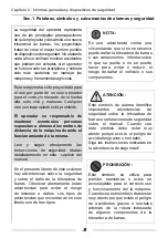
Page 106: ...e advertencias que encontrarán en este libreto son de tres tipos ATENCIÓN Este símbolo de alarma identifica importantes advertencias de seguridad sobre la trituradora de barras o señalaciones de seguridad sobre el manual Cuando vea este símbolo debe estar muy atento porque exis te el peligro de accidentes graves o mortales Siga las instrucciones indicadas en la advertencia de seguridad NOTA Es una...

Page 107: ...áquina Trabajar en seguridad Prestar atención a los demás Es VUESTRA responsabilidad leer y comprender este manual y el libreto de las Normas generales de seguridad anexado antes de utilizar la trituradora de barras Deberá efectuar estas normas de seguridad que los acompañará durante vuestra jornada de trabajo Recuerde siempre que USTED es elresponsable de vuestra seguridad Buenas normas de seguri...

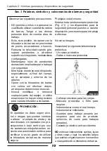
Page 108: ...mbiar o alterar el estado de alerta y de coordinación Un operador con pre scripciones o bajo control por uso de sustancias estupefacientes ne cesita una autorización médica para certificar si es en grado de utilizar la trituradora de barras de manera segura Capítulo 2 Normas generales y dispositivos de seguridad Sec 1 Palabras símbolos y calcomanías de alarmas y seguridad Protéjase usted mismo End...

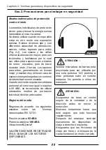
Page 109: ... recomienda de utilizar adecuados medios de protección individual del oído adecuados Registro del medio Registros de acuerdo los siguientes estudios sobre las Normas Armonizadas EN 12733 Presión acústica 92 dBA Potencia acústica 106 dBA Vibraciones 9 3 m s2 VALORES MÁXIMOS REGISTRADOS EN LA GAMA DE LOS MOTORES DISPONIBLES Capítulo 2 Normas generales y dispositivos de seguridad Sec 2 Precauciones p...

Page 110: ...EAR LAS PALANCAS DE AVANCE DE LA MAQUINA Y MOVItMIENTO DE LAS CUCHILLAS PARA PODER OPERAR CON LA HERRAMIENTA EXISTE EL PELIGRO DE ACCIDENTE GRAVES O MORTALES La palanca de embrague rotor cuchillas siempre se debe accionar con las dos manos Desenganche el acople de seguridad de la palanca de embrague rotor cuchillas como se ilustra Fig 2 4 Nunca opere sobre terrenos con una pendiente lateral superi...

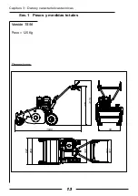
Page 111: ...13 Versión TS 50 Peso 125 Kg Dimensiones 1640 968 1115 658 543 577 667 548 50 Capítulo 3 Datos y características técnicas Sec 1 Pesos y medidas totales ...

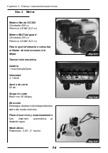
Page 112: ...4 8 kW 6 5 cv Para mayor información consultar el libreto de instrucciones del Motor Transmisión mecánica Cambio 1 marchas adelante Velocidad 2 1 Km h Ancho de corte 50 cm Grupo de corte Rotor con 26 látigos Dirección Embrague de dirección independientes sobre las rueda motrices Freno de servicio y estacionamiento Con inserción automática al desembrague Neumáticos Posteriores 4 00 4 tractor ...

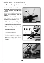
Page 113: ...os comando aquí citados es necesario leer atentamente el Capítulo 5 Uso 1 Palanca desbloqueo rueda izquierda 2 Palanca embrague avance máquina 3 Palanca desbloqueo rueda derecha 4 Manecilla mando gas 5 Palanca embrague rotor 6 Acople de seguridad embrague rotor 7 Palanca regulación en alteza y lateral manubrio Capítulo 4 Mandos e instrumentos de control Sec 1 Descripción de los mandos 1 2 Fig 4 1 ...

Page 114: ... los mandos 9 8 10 Fig 4 4 11 12 13 Fig 4 5 14 Fig 4 6 8 Tapa depósito carburante 9 Tapa aceite transmisión 10 Varilla nivel aceite motor 11 Palanca Starter para motores a gasolina 12 Interruptor motor ON OFF 13 Manija arranque motor 14 Palanca regulación alteza corte ...

Page 115: ...regular la alteza del manubrio en base a la propia estatura y a la naturaleza del terreno llano o montañoso Para alzar o bajar el manubrio es necesario intervenir sobre la palanca Fig 4 7 colocada en la base de las manceras Además es posible obtener una regulación lateral del manubrio para poder operar cerca de pozos y en las orillas El manillar puede asumir varias posiciones a derecha e izquierda...

Page 116: ...sea al máximo para tener una lubricación segura y óptima En caso de llenado utilicen solo aceite ESSO UNIFARM 15 40 W Para mayor información consultar el libreto de instrucciones del motor Antes de poner en marcha la segadora de cuchillas Verifique por su seguridad que las palancas de avance máquina y activación rotor cuchillas estén en posición vertical Fig 5 1 1 2 Fig 5 1 9 8 10 Fig 5 2 PROHIBIC...

Page 117: ...ta esta operación dando siempre golpes secos y decididos hasta que el motor se encienda Una vez que el motor se ha encendido se aconseja dejarlo girar a vacío un instante permitiendo al aceite de alcanzar todos los órganos en movimiento Para apagar el motor basta posicionar el interruptor ON OFF en OFF 12 el motor se detendrá en pocos segundos 5 Fig 5 3 11 12 13 Fig 5 4 Capítulo 5 Uso Sec 1 Encend...

Page 118: ... que está bloqueada por un acople de seguridad Fig 5 8 Este acople pensado para vuestra seguridad e impide que el operador pueda inserir el rotor cuchillas mientras la trituradora de barras se encuentra en movimiento sino sólo con la máquina detenida Fig 5 5 1 2 Fig 5 8 p Es necesario utilizar dos manos para desenganchar la palanca que está bloqueada por un acople de seguridad Fig 5 8 Fig 5 9 ATEN...

Page 119: ...las durante el avance Capítulo 5 Uso Sec 3 Palancas desbloqueo ruedas DCH IZQ Fig 5 10 25 Fig 5 11 ATENCIÓN Si se trabaja en pendiente Fig 5 11 NO utilice simultáneamente las palancas desbloqueo ruedas DER IZQ de este modo se excluye automáticamente el freno de estacionamiento y se anula su función de seguridad Suelte la palanca embrague avance máquina las rueda se bloquean inmediatamente y el fre...

Page 120: ...abre o se cierra en función del volumen de la hierba a cortar Si la alteza de corte se regula demasiado baja podrían verificarse los siguientes efectos negativos proyección hacia el externo de objetos extraños como piedras etc acumulación de tierra y fango en el interior del cárter de protección del rotor Por consiguiente la descarga de la hierba no se producirá regularmente veloz desgaste de las ...

Page 121: ...iable ATENCIÓN la mezcla de gasolina y de alcohol no está aprobada dada la eventual lubricación insuficiente del sistema de inyección combustible ATENCIÓN No llene el depósito completamente Deje espacio para el aumento del volumen Si la tapa original se pierde sustitúyala con una repuesto original y apriétela a fondo PROHIBICIÓN Con el motor en movimiento nunca retire la tapa ni hagan abastecimien...

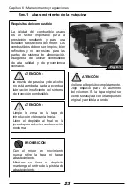
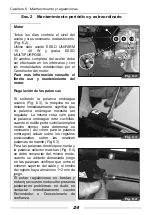
Page 122: ...e para la palanca embrague rotor cuchillas cuando el rodillo porta cuchillas emplea mucho tiempo para detenerse es necesario así como para la palanca embrague actuar sobre los registros posicionados sobre las relativas palancas de mando Fig 6 3 Para las palancas desbloqueo rueda y la palanca selector marchas Fig 6 4 se debe comportar del mismo modo cuando se advierte demasiado juego en las palanca...

Page 123: ...1 1 OBSàUGA I KONSERWACJA PL ...

Page 124: ...aá 3 Dane i parametry techniczne 13 Cz 1 Ciężary i wymiary gabarowe 13 Cz 2 Silnik i informacje ogólne 14 Rozdziaá 4 Elementy i przyrządy sterownicze 15 Cz 1 Opis elementów sterowniczych 15 Cz 2 Dźwignie regulujące wysokość i położenie boczne uchwytu 17 Rozdziaá 5 Obsáuga 18 Cz 1 Uruchamianie zatrzymywanie silnika 18 Cz 2 Dźwignia sprzęgła napędu urządzenia i ruchu ostrzy 20 Cz 3 Dźwignie odblokow...

Page 125: ...ych części zamiennych i są w stanie udzielić porad w zakresie ich montażu i użytkowania Stosowanie części zamiennych gorszej jakości może spowodować poważne uszkodzenia Z tego powodu zaleca się nabywanie niezbędnych części zamiennych wyłącznie u autoryzowanych sprzedawców Z uwagi na znaczne różnice warunków eksploatacyjnych producent nie jest w stanie dostarczyć idealnie zaktualizowanych publikacj...

Page 126: ...obsługi maszyn i urządzeń rolniczych Należy uważnie przeczytać zalecenia dotyczące bezpieczeństwa przedstawione w niniejszym rozdziale instrukcji i dokładnie ich przestrzegać Jeżeli nie podano inaczej dane i informacje przedstawione w niniejszej instrukcji obsługi mają zastosowanie do wszystkich modeli Treść niniejszej instrukcji obsługi jest zgodna z najnowszymi informacjami technicznymi dostępny...

Page 127: ...danych w celu zapewnienia szybkiej i sprawnej obsługi podczas zamawiania części zamiennych lub żądania informacji lub objaśnień technicznych Silnik identyfikowany jest poprzez dane wytłoczone na odpowiedniej tabliczce umieszczonej z jego boku Rys 1 3 Zaleca się zapisanie takich danych w celu zapewnienia szybkiej i sprawnej obsługi podczas zamawiania części zamiennych lub żądania informacji lub obj...

Page 128: ... objęte muszą być wszystkie osoby obsługujące lub konserwujące kultywator Prawidłowo przeprowadzona instalacja w połączeniu z regularną konserwacją pomagają zapobiec usterkom Gdyby mimo to wystąpiły jakiekolwiek problemy z działaniem urządzeniawokresiegwarancyjnym zaleca się przestrzeganie następującej procedury niezwłocznie powiadomić o problemie sprzedawcę u którego został zakupiony kultywator p...

Page 129: ...amontować przed użyciem kosiarki bijakowej W okresie obowiązywania gwarancji zaleca się powierzanie wszystkich napraw i konserwacji sprzedawcy który w ten sposób będzie w stanie na bieżąco kontrolować działanie i wydajność nowo nabytej kosiarki bijakowej Aby zachować optymalną wydajność kosiarki bijakowej nie należy przerywać regularnych przeglądów konserwacyjnych i serwisowania również po upływie...

Page 130: ...pieczenia Cz 1 Sáowa symbole oraz znaki alarmowe i bezpieczeĔstwa Z uwagi na to że bezpieczeństwo operatora stanowi jeden z głównych priorytetów projektantów urządzeń podczas prac nad nową kosiarką bijakową starają się oni zastosować maksymalną możliwą liczbę zabezpieczeń Mimo to co roku dochodzi do wielu wypadków których można by było uniknąć gdyby operator mniej się spieszył i zachował większą o...

Page 131: ...nejbroszuryzawierającejdyspozycje ogólne dotyczące bezpieczeĔstwa przed użyciem kosiarki bijakowej Podczas pracy należy zawsze przestrzegać wszystkich przepisów i zaleceń dotyczących bezpieczeństwa Użytkownik powinien zawsze pamiętać iż to ON SAM odpowiada za własne bezpieczeństwo Przepisy dotyczące bezpieczeństwa chronią nie tylko użytkownika ale również osoby przebywające w jego pobliżu UŻYTKOWN...

Page 132: ... do posiadanej kosiarki bijakowej ZAKAZ Operator nie może być spożywać alkoholu lub zażywać narkotyków wpływających na czujność i koordynację Operator zażywający substancje odurzające z przepisu lekarza lub pod kontrolą musi uzyskać zaświadczenie lekarskie poświadczające że jest w stanie obsługiwać kosiarkę bijakową w bezpieczny sposób Należy chronić własne bezpieczeństwo Należy nosić odpowiednią ...

Page 133: ...nich indywidualnych środków ochrony słuchu Pomiary dla urządzenia Pomiary zgodne z następującymi studiami nad normami zharmonizowanymi EN 12733 Ciśnienie akustyczne 92 dBA Moc akustyczna 106 dBA Drgania 9 3 m s MAKSYMALNE WARTOŚCI ZMIERZONE W GAMIE DOSTĘPNYCH SILNIKÓW Rozdział 2 Dyspozycje ogólne i zabezpieczenia Cz 2 ĝrodki ostroĪnoĞci związane z bezpieczną pracą Fig 2 2 BACZNOĝû Kosiarka bijakow...

Page 134: ...promieniu 10 metrów nie przebywają żadne osoby W przypadku wykonywania pracy w miejscu w którym znajduje się duża ilość kamieni lub innych przeszkód przed rozpoczęciem cięcia należy usunąć ich jak największą ilość Mimo zabezpieczeń istnieje ryzyko iż kamienie lub inne ciała obce mogą zostaćwyrzuconewkierunkuoperatora lub innych osób znajdujących się w pobliżu Podczas pracy stacjonarnej z kosiarką ...

Page 135: ...13 Wersja TS 50 Waga 125 Kg Wymiary 1640 968 1115 658 543 577 667 548 50 Rozdział 3 Dane i parametry techniczne Cz 1 CiĊĪary i wymiary gabarytowe ...

Page 136: ... W celu uzyskania dodatkowych informacji naleĪy siĊ zapoznaü z instrukcją obsáugi silnika NapĊd mechaniczny Skrzynia biegów 1 biegi do przodu PrĊdkoĞü 2 1 Km h SzerokoĞü ciĊcia 50 cm Zespóá tnący Wirnik z 26 bijakami Kolumna kierownicza Niezależne sprzęgła kolumny kierowniczej na kołach napędowych Hamulec roboczy i postojowy Włączający się automatycznie po zwolnieniu sprzęgła Opony Tylne 4 00 4 ci...

Page 137: ...ch poniżej należy uważnie przeczytać rozdział 5 Obsługa 1 Dźwignia odblokowująca lewe koło 2 Dźwignia sprzęgła napędu urządzenia 3 Dźwignia odblokowująca prawe koło 4 Pokrętło sterujące gazem 5 Dźwignia włączająca wirnik 6 Zaczep bezpieczeństwa włączania wirnika 7 Dźwignia regulująca wysokość położenie boczne uchwytu 1 2 Fig 4 1 3 5 4 6 Fig 4 2 7 Fig 4 3 Rozdział 4 Przyciski i elementy sterownicze...

Page 138: ... oleju przekładniowego 10 Miarka poziomu oleju silnikowego 11 Dźwignia rozrusznika dla silników benzynowych 12 Przełącznik silnika ON OFF 13 Uchwyt uruchamiający silnik 14 Dźwignia regulująca wysokość cięcia Rozdział 4 Przyciski i elementy sterownicze Cz 1 Opis elementów sterowniczych ...

Page 139: ...bliżu rowów i brzegów Uchwyt można ustawić w kilku poáoĪeniach po prawej i lewej stronie Aby przesunąć uchwyt bocznie należy odkręcić dźwignię Rys 4 8 a następnie przesunąć uchwyt w prawo lub w lewo Aby ponownie zablokować uchwyt należy przykręcić dźwignię sprawdzając czy podstawa kierownicy jest prawidłowo wsunięta Fig 4 7 Fig 4 8 Fig 4 9 BACZNOĝû Jeżeli pracuje się przez wiele godzin należy star...

Page 140: ...ełniania oleju należy stosować wyłącznie olej ESSO UNIFARM 15 40 W W celu uzyskania dodatkowych informacji należy się zapoznać z instrukcją obsługi silnika Przed uruchomieniem kosiarki bijakowej należy Sprawdzić dla własnego bezpieczeństwa czy dźwignie napędu urządzenia i uruchamiająca wirnik ostrzy znajdują się w położeniu pionowym Rys 5 1 Przesunąć pokrętło sterowania gazem 5 do połowy Rys 5 2 1...

Page 141: ...nia silnika Po uruchomieniu silnika zaleca się pozostawienie go na chwilę na obrotach jałowych aby umożliwić dotarcie oleju do wszystkich poruszających się części W celu wyłączenia silnika wystarczy ustawić przełącznik ON OFF w położenie wyłączone czyli OFF Rys 5 6 Silnik zatrzyma się w ciągu kilku sekund 5 Fig 5 3 11 12 13 Fig 5 4 W celu wyłączenia silnika wystarczy ustawić przełącznik ON OFF w p...

Page 142: ...ecznie uĪywaü obu rąk Rys 5 8 Ten zaczep zaprojektowany został z myślą o bezpieczeństwie użytkownika i uniemożliwiaoperatorowiuruchomienie wirnika z ostrzami podczas gdy kosiarka bijakowa jest w ruchu jest to możliwe dopiero po jej zatrzymaniu Fig 5 5 1 2 Fig 5 8 Do odczepiania dĨwigni zablokowanej przez zaczep zabezpieczający naleĪy koniecznie uĪywaü obu rąk Rys 5 8 Fig 5 9 BACZNOĝû W razie trudn...

Page 143: ...Obsługa Cz 3 DĨwignie odblokowujące koáa prawe lewe Fig 5 10 25 Fig 5 11 BACZNOĝû Podczas pracy na nachyleniach Rys 5 11 NIE należy równocześnie używać dźwigni odblokowujących koło prawe i lewe gdyż spowodowałoby to automatyczne zwolnienie hamulca postojowego pełniącego funkcję zabezpieczenia Zwolnić dźwignię sprzęgła napędu urządzenia koła zablokują się natychmiast a hamulec postojowy zostanie za...

Page 144: ...wencji wyrzut trawy nie może przebiegać w prawidłowy sposób Szybkie zużycie ostrzy i ryzyko ich złamania Osłona przednia Rys 5 14 otwiera się lub zamyka w zależności od objętości ścinanej trawy Fig 5 12 Fig 5 14 Fig 5 15 ZAKAZ NIE wolno nigdy używać urządzenia z otwartą osłoną Mogłoby to spowodować odrzut ciał obcych Osłona może być zamocowana w pozycji otwartej tylko podczas wymiany noży której d...

Page 145: ...nie jest dozwolona z uwagi na potencjalne niedostateczne smarowanie systemu wtrysku paliwa BACZNOĝû Oczyścić okolice korka wlewu i utrzymywaćjewczystości Napełnić bak pod koniec każdego dnia aby zmniejszyć skraplanie nocne ZAKAZ Gdy silnik jest włączony nie wolno nigdy odkręcać korka wlewu ani tankować urządzenia Podczas napełniania baku należy zawsze zachować kontrolę nad pistoletem do tankowania...

Page 146: ...ie nie zatrzymuje się natychmiast oznacza to że dźwignia sprzęgła napędu wymaga regulacji To samo dotyczy dźwigni sprzęgła uruchamiającego wirnik ostrzy jeżeli wałek ostrzy potrzebuje dłuższego czasu aby się zatrzymać należy podobnie jak w przypadku dźwigni sprzęgła zadziałać na śruby regulacyjne znajdujące się na odpowiednich dźwigniach sterowniczych Rys 6 3 W przypadku dźwigni odblokowujących ko...

Page 147: ...ión de serie 3 serie identifi ceren è conforme alle prescrizioni della direttiva complies with the requirements established by directive est conforme aux spécifi cations de la directive den Bestimmungen des Erlasses cumple los requisitos de la directiva voldoet aan de voorschriften van richtlijn è conforme alle disposizioni delle seguenti norme armonizzate conforms with the provisions of the followi...

Page 148: ...dentifi kacija 3 Серийный номер 3 Numer serii está conformemente às prescriçoes da diretriz κατασκεναζεται συμφωνα με την οδηγια müteakip direktifi n gerekliliklerine uygundur odgovarja zahtevam podanih v smernicah соответствует предписаниям директивы jest zgodna z przepisami dyrektywy está em conformidade com as disposições das seguintes normas harmonizadas συμμορφούται με διατάξεις των ακόλουθων ε...

Page 149: ...brato dal rivenditore compilato in tutte le sue parti e corredato di fattura d acquisto o scontrino fiscalmente obbligatorio compro vante la data d acquisto 4 La garanzia decade in caso di Assenza palese di manutenzione Utilizzo non corretto del prodotto o manomis sioni Utilizzo di lubrificanti o combustibili non adat ti Utilizzo di parti di ricambio o accessori non originali Interventi effettuati...

Page 150: ...é de la facture ou du reçu de caisse qui doit obli gatoirement être remis pour prouver la date d achat 4 La garantie perd toute valeur en cas de Manque évident d entretien CERTIFICAT DE GARANTIE Utilisation incorrecte ou transformations non autorisées du produit Utilisation de lubrifiants ou de combustibles inappropriés Utilisation de pièces de rechange ou d acces soires non d origine Intervention...

Page 151: ...dig ausgefüllte Garantieschein zusammen mit der Rechnung bzw dem Kassenzettel zum Nachweis des Kaufdatums vorgelegt werden 4 In folgenden Fällen verfällt jeder Garantiean spruch Bei offensichtlicher Unterlassung der War GARANTIE ZERTIFICAT tung Bei nicht korrekter Verwendung oder Verän derungen des Produkts Bei Benutzung von ungeeigneten Schmiermit teln oder Treibmitteln Bei Benutzung von nicht or...

Page 152: ...howing the date of purchase must be displayed to the person nel authorised to approve work 4 The warranty shall be null and void if the machine has evidently not been serviced correctly WARRANTY CERTIFICATE the machine has been used for improper purposes or has been modified in any way unsuitable lubricants and fuels have been used non original spare parts and accessories have been fitted work has...

Page 153: ...izado asimismo para que el certificado sea válido se han de completar todas sus partes y ha de estar debidamente timbrado por el vendedor 4 La garantía pierde su validez en los siguientes casos CERTIFICADO DE GARANTÍA Falta evidente de mantenimiento Uso incorrecto o manipulación del producto Uso de lubricantes o combustibles inadecua dos Uso de piezas de recambio o accesorios no originales Interve...

Page 154: ...karty gwarancyjnej opatrzonej pieczątką sprze dawcy oraz faktury zakupu maszyny lub stosownego rachunku na którym widnieje data zakupu 4 Gwarancja nie obejmuje uszkodzeń powstałych na skutek ewidentnego KARTA GWARANCYJNA braku konserwacji uszkodzeń powstałych na skutek niewłaściwej eksploatacji uszkodzeń powstałych na skutek stosowania niewłaściwych smarów lub paliw uszkodzeń powstałych na skutek ...

Page 155: ......
Page 156: ...eft muß das Gerät während seiner gesamten Lebensdauer begleiten WARNING This owner s manual must stay with the machine for all its life ATENCION Este manual debe acompañar a la máquina durante toda su vida útil UWAGA Niniejsza instrukcja powinna towarzyszyc urzadzeniu przez caly okres jego eksploatacji DR55H6 5 WB55H6 5 NTS 50 68240078B Ott 2010 Member of the YAMA group 42011 Bagnolo in Piano RE I...

Reviews: