Pubbl. 68320142A - Gen/2015
I
D
F
GB
E
NL
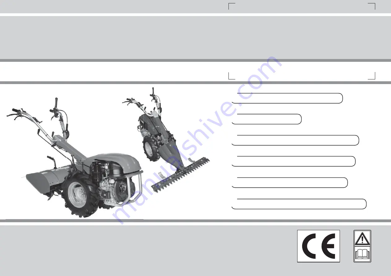
OWNER’S MANUAL
MANUALE USO E MANUTENZIONE
BETRIEBS- UND WARTUNGSANLEITUNG
MANUEL D’UTILISATION ET D’ENTRETIEN
MANUAL DE USO Y MANTENIMIENTO
GEBRUIKS- EN ONDERHOUDSHANDLEIDING
Page 1: ... 68320142A Gen 2015 I D F GB E NL OWNER S MANUAL MANUALE USO E MANUTENZIONE BETRIEBS UND WARTUNGSANLEITUNG MANUEL D UTILISATION ET D ENTRETIEN MANUAL DE USO Y MANTENIMIENTO GEBRUIKS EN ONDERHOUDSHANDLEIDING ...
Page 2: ...ventuelle Veränderungen vorzunehmen ohne jeweils vorher eine Anpassung der vorliegenden Bedienungsanleitung vorzunehmen E INTRODUCCION TRADUCCIÓN DE LAS INSTRUCCIONES ORIGINALES Para utilizar correctamente el motocultivador y evitar accidentes lea atentamente este manual antes de comenzar el trabajo Ud encontrará las explicaciones de funcionamiento de los diferentes componentes y las instrucccione...
Page 3: ... not available on your machine depending on the selected equipment option and the market in which the machine was bought ATENCIÓN Es posible que algún dispositivo descrito en el manual no se encuentre en todas las máquinas esto depende del equipamiento escogido y del país de uso F NL ATTENTION Il est possible que certains dispositifs décrits dans le manuel ne soient pas présents sur votre machine ...
Page 4: ..._________ 86 MAINTENANCE CHART______________ 88 TROUBLE SHOOTING CHART _________ 91 WARRANTY CERTIFICATE ____________ 94 INTRODUCCION ___________________ 2 DECLARACION DE CONFORMIDAD ____ 5 COMPONENTES DEL MOTOCULTIVADOR_________________ 6 EXPLICACION SIMBOLOS Y ADVERTENCIÂS DE SEGURIDAD ______ 8 NORMAS DE SEGURIDAD____________ 16 MONTAJE ________________________ 19 PUESTA EN MARCHA ______________...
Page 5: ...e 3 identificazione di serie 3 serial identification 3 identification de série 3 Serien Identifizierung 3 identificación de serie 3 serie identificeren è conforme alle prescrizioni della direttiva complies with the requirements established by directive est conforme aux spécifications de la directive den Bestimmungen des Erlasses cumple los requisitos de la directiva voldoet aan de voorschriften va...
Page 6: ...in gauche 19 Blocage levier frein D BAUTEILE DES EINACHSSCHLEPPERS 1 Ein Aus Schalter 2 Griffholm 3 Totmannschalter 4 Sperre für Totmannschalter 5 Kupplungshebel 6 Sperre für Kupplungshebel 7 Hebel für Lenkholm Seitenverstellung 8 Schalthebel für Zapfwelle 9 Hebel für Wendegetriebe 10 Sperrhebel für Differentialgetriebe Bertolini 411 Nibbi Kam 5 Mak 5 Fog 11 Batterieaufnahme 12 Schalthebel 13 Senk...
Page 7: ...nt barre 11 Patin 12 Barre de fauchage 13 Fourreau protège lames D ZUSÄTZLICHE BAUTEILE 1 Startschalter 2 Batterie Ladekontrollleuchte 3 Öldruck Kontrollleuchte 4 Einpolige Steckbuchse für Arbeitsscheinwerfer 5 Motor Aus Schalter 6 Zapfwellenanschluss 7 Arbeitswerkzeuge 8 Sporn für Arbeitstiefe 9 Fräsenschutzgehäuse 10 Mähbalkenantrieb 11 Gleitkufe 12 Mähbalken 13 Messerabdeckung E OTROS COMPONENT...
Page 8: ... 1 Betriebsanleitung vor der Inbetriebsnahme lesen 2 N Leerlauf I Einlegen 1 Gang II Einlegen 2 Gang III Einlegen 3 Gang 3 Kupplungshebel 4 Gashebel 5 Bremsbetätigung 6 Lenkholm Schwenkrichtung E 1 Antes de utilisar esta maquina leer el manual de instrucciones 2 N punto muerto I primera marcha II segunda marcha III tercera marcha 3 Mando del embrague 4 Mando del acelerador 5 Mando del freno 6 Sent...
Page 9: ...7 Differentialsperre ein 8 Differentialsperre aus 9 Gang einlegen und Zapfwelle einschalten 10 Fahrtrichtung vorwärts mit Heckgeräten 11 Fahrtrichtung vorwärts mit Frontgeräten 12 ACHTUNG Heiße Oberflächen E 7 Bloqueo del diferencial 8 Desbloqueo del diferencial 9 Conexión de marchas y toma de fuerza 10 Sentido de avance en configuración para aperos traseros 11 Sentido de avance en configuración p...
Page 10: ... Numéro de série 16 Label CE de conformité 17 Type de machine MOTOCULTEUR 18 Année de construction 19 Ne pas placer les mains ou les pieds à proximité du carter de lame lorsque le moteur est en marche ATTENTION Les lames restent en movement pour quelques secondes même après que le moteur a été éteint D 13 Marke und Maschinenmodell 14 Technische Daten 15 Seriennummer 16 CE Zeichen 17 Gerät EINACHSS...
Page 11: ...Eloigner les mains et les pieds Ne pas nettoyer l outil moteur en marche 23 La batterie est fournie au départ sans acide Respecter les instructions du manuel pour le remplissage 24 La recharge de la batterie doit durer au moins 4 heures Suivre les instructions du manuel pour la recharge D 20 Betriebsanleitung vor der Inbetriebnahme lesen 21 Immer Helm Schutzbrille und Geräuschschutz tragen 22 ACHT...
Page 12: ... esempio cuffie o tappi per le orecchie Indossare guanti che permettano il massimo assorbimento delle vibrazione Fig 3 4 5 6 7 Consentire l uso del motocoltivatore soltanto a persone che hanno letto questo manuale di uso e manutenzione o che hanno ricevuto istruzioni adeguate per un uso sicuro e appropriato del motocoltivatore 8 Controllare giornalmente il motocoltivatore per assicurarsi che ogni ...
Page 13: ...llow others to use the rotary cultivator who have read this operator s manual or received adequate instructions for the safe and proper use of the rotary cultivator 8 Check the rotary cultivator daily to ensure that all safety and other devices are fully operational 9 Never use a damaged modified or improperly repaired or assembled rotary cultivator Do not remove damage or deactivate any of the sa...
Page 14: ...ortez des lunettes de protection ou un masque Utilisez des protections antibruit notamment un casque antibruit ou des protège tympan Portez des gants capables d absorber au maximum les vibrations Fig 3 4 5 6 7 Ne permettre l utilisation du motoculteur qu à des personnes qui ont lu ce manuel d utilisation et d entretien ou qui ont reçu des instructions adéquates pour une utilisation sûre et appropr...
Page 15: ... 3 4 5 6 7 Die Bedienung des Einachsschleppers ausschließlich den Personen gestatten die das vorliegende Betriebs und Wartungshandbuch gelesen haben und die in angemessener Weise in den sicheren und sachgerechten Einsatz des Einachsschleppers eingewiesen worden sind 8 Den Einachsschlepper täglich auf die einwandfreie Funktion der Sicherheits und anderen Vorrichtungen überprüfen 9 Beschädigte umger...
Page 16: ...oídos Póngase guantes protectores con el máximo poder de absorción de vibraciones Fig 3 4 5 6 7 Este motocultivador debe ser utilizado solo por personas que hayan leído este manual o que hayan recibido las debidas instrucciones para un manejo correcto y seguro 8 Controle el motocultivador a diario para cerciorarse de que todos los dispositivos funcionen correctamente incluidos los de seguridad 9 N...
Page 17: ... hebben gelezen of als ze passende instructies hebben gekregen over het correcte en veilige gebruik van deze motorploeg 8 Controleer de motorploeg dagelijks om er zeker van te zijn dat elk onderdeel voor de veiligheid of anderszins goed werkt 9 Gebruik nooit een beschadigde gewijzigde of onjuist gerepareerde of geassembleerde motorploeg Verwijder of beschadig geen enkele veiligheidsvoorziening en ...
Page 18: ...e Quickfit C Fig 3 ensuring that its coupling surface is snugly seated Screw down the three nuts A Fig 3 Fitting the cutterbar Raise the accessories locking lever D Fig 4 on the Quickfit Grease the coupling components Fully insert the cutterbar body coupling E Fig 4 Lower lever D Fig 5 to lock the accessory in place Note If the locking lever D Fig 5 does not lower fully after the accessory has bee...
Page 19: ...Levante la palanca de bloqueo de los accesorios D Fig 4 del Quickfit Engrase las piezas de acoplamiento Inserte el vástago de la barra segadora E Fig 4 hasta el tope Baje la palanca D Fig 5 para bloquear la barra Nota si la palanca de bloqueo de los accesorios D Fig 5 no se baja por completo después del montaje mueva el accesorio para que el perno de la palanca se encaje en el orificio del vástago...
Page 20: ...hat the cables do not become trapped and consequently damaged Fig 11 3 Push the handlebar horizontal adjustment lever I towards the steering column back to its original position thereby locking the steering column 4 Reinsert the power take off engagement lever and gearshift lever into mounts H Fig 10 WARNING After every rotation of the handlebar make sure that the safety components are in perfect ...
Page 21: ...anillar I a la posición original hacia el tubo de dirección para bloquear el tubo 4 Coloque la palanca de la toma de fuerza y la palanca de las marchas en los soportes H Fig 10 ATENCIÓN Después de cada rotación del manillar manceras controle que los dispositivos de seguridad funcionen correctamente Para devolver el manillar a la posición para aperos frontales efectúe la operación de rotación en se...
Page 22: ... accessoire pour permettre à l axe du levier de s encastrer dans le trou de l enclenchement du corps de la fraise Montage roues Monter les roues sur les moyeux du motoculteur à l aide des 4 vis G comme indiqué figure 19 ATTENTION contrôler que la flèche sur la chape des pneumatiques est tournée vers le sens de l avance A Fig 19 PREPARAZIONE PER IL LAVORO PREPARING FOR WORK PRÉPARATION DU TRAVAIL F...
Page 23: ...endel van de accessoires D afb 18 niet volledig omlaag kan worden gebracht nadat het accessoire geplaatst is beweeg het accessoire dan om ervoor te zorgen dat de pen van de hendel in het gat van de koppeling van de behuizing van de frees wordt geklemd Montage van de wielen Monteer de wielen op de naven van de motorploeg met de 4 schroeven G zoals in de afbeelding 19 LET OP controleer of de pijl di...
Page 24: ... to release pressure and to keep fuel from escaping around the cap Tighten fuel cap securely after refuelling Unit vibration can cause an improperly tightened fuel cap to loosen or come off and spill quantities of fuel Wipe spilled fuel from the unit and allow remaining fuel to evaporate Move 3 m away from refuelling site before starting engine Never attempt to burn off spilled fuel under any circ...
Page 25: ...amente el tapón del depósito de combustible para liberar la presión y evitar que el combustible se escape alrededor del tapón Apriete firmemente el tapón del depósito de combustible después de cargar el combustible Si el tapón del depósito no está correctamente apretado las vibraciones de la unidad pueden provocar que el tapón se afloje o se salga y se derrame combustible Elimine de la unidad el c...
Page 26: ...n oil gasoline mixture Avoid getting dirt or water in the fuel tank Filling the Tank WARNING Follow safety instruction for fuel handling Always shut off engine before fuelling Never add fuel to a machine with a running or hot engine Move at least 3 m from refuelling site before starting engin DO NOT SMOKE 1 Clean surface around fuel cap to prevent contamination 2 Loosen fuel cap slowly 3 Carefully...
Page 27: ...nstrucciones de seguridad relativas al manejo de combustible Apague siempre el motor antes de repostar No añada nunca combustible a una máquina mientras el motor esté en marcha o caliente Aléjese al menos 3 metros del lugar de recarga de combustible antes de arrancar el motor NO FUME 1 Limpie la superficie alrededor del tapón del depósito de combustible para evitar la contaminación 2 Afloje lentam...
Page 28: ...THE ENGINE MANUAL Add the engine oil slowly to avoid overflowing as the engine oil tank capacity is small If the engine is operated continuously check the engine oil level every 10 hours Use 4 stroke or an equivalent high detergent premium quality motor oil certified to meet or exceed U S automobile manufacturer s requirements for service classifications SG SF Motor oils classified SG SF will show...
Page 29: ...amente para evitar que rebose la capacidad del depósito de aceite es reducida Si el motor se utiliza de manera continua controlar el nivel del aceite cada 10 horas de uso Utilice aceite para motores de 4 tiempos o cualquier otro de alto grado detergente y máxima calidad con certificado de que cumple o supera los requisitos de los fabricantes de automóviles para la clasificación de servicio SG SF L...
Page 30: ...see figure 34 Move the gearshift lever to the neutral position N Fig 35 Operate the brake levers A B Fig 40 locking them with the specific latches C Fig 40 Set the power take off control lever to the disengaged position if using front implements push the lever R Fig 36 if using rear implements pull the lever R Fig 37 Set the switch A Fig 38 to ON or the lever A Fig 39 to I Set the throttle lever B...
Page 31: ...nto muerto N Fig 35 Accione las palancas del freno A y B Fig 40 y bloquéelas con las fijaciones C Fig 40 Ponga la palanca de la toma de fuerza en posición de desconexión con aperos frontales empuje la palanca R Fig 36 con aperos traseros tire de la palanca R Fig 37 Ponga el interruptor A Fig 38 en la posición ON o la palanca A Fig 39 en la posición I Lleve la palanca del acelerador B Figs 38 39 a ...
Page 32: ...olyte comes into contact with eyes rinse with plenty of water and seek immediate medical advice DO NOT SMOKE AND KEEP AWAY FROM OPEN FLAMES AND SPARKS Fill the elements with sulphuric acid with a density of 1270 1280 g l at 20 C until the level is approximately 5 mm above the top of the separators Let the battery rest for about 30 minutes and if necessary correct the levels Note Immediately remove...
Page 33: ...cto del electrolito con los ojos lavar con abundante agua y acudir a un médico NO FUME Y EVITE LA PRESENCIA DE LLAMAS Y CHISPAS Llene los elementos con ácido sulfúrico de densidad 1270 1280 g l referida a una temperatura de 20 C hasta que el nivel sobrepase en 5 mm el borde de los separadores Deje las baterías en reposo durante media hora y si es necesario restablezca los niveles Nota seque de inm...
Page 34: ... in critical conditions In the case of batteries subject to deep discharge or that have been left discharged for extended periods 15 days it is advisable to charge the battery at a constant current of 0 5 1 0 A for at least 10 12 h then proceed with normal charging as specified above Fitting the battery Open the cowling A Fig 45 and fit the battery in the specific housing as shown in figure 46 Whe...
Page 35: ...ía se ha descargado en exceso o ha permanecido descargada durante más de 15 días se aconseja cargarla con corriente constante de 0 5 1 A durante al menos 10 12 h y después continuar la carga como se indicó anteriormente Montaje de la batería Levante el capó A Fig 45 y coloque la batería en su alojamiento como en la figura 46 Durante el montaje de la batería tenga cuidado de no aplastar los cables ...
Page 36: ...with petrol engine Read the engine user manual For all other models Turn the key C to I the battery warning lamp D and oil pressure warning lamp E optional should light up Fig 58 Note The battery warning lamp C should switch off as soon as the engine starts whereas the oil warning lamp D optional switches off as soon as the engine oil is pressurised Fig 58 Turn the key C to START and release it wh...
Page 37: ... Consulte el manual de uso y mantenimiento del motor Para todos los demás modelos Gire la llave C a la posición I los testigos de batería D y presión de aceite E opcional se deben encender Fig 58 Nota El testigo de la batería C se debe apagar cuando se enciende el motor mientras que el testigo del aceite D opcional se apaga cuando el aceite llega a la presión de trabajo Fig 58 Gire la llave C a la...
Page 38: ... to the idle position before changing gear To change gear use the gearshift lever G When using front implements the lever G is on the operator s right hand side Fig 64A When using rear implements lever G is on the operator s left hand side Fig 64B Note On guard F of the steering column Fig 65 66 there is a label illustrating the correct gear sequence If using front implements see the yellow part o...
Page 39: ...Cuando se utilizan aperos frontales la palanca G está a la derecha del conductor Fig 64A Cuando se utilizan aperos traseros la palanca G está a la izquierda del conductor Fig 64B Nota La etiqueta aplicada a la carcasa F del tubo de dirección Figs 65 66 ilustra la secuencia correcta de marchas Para el uso de aperos frontales ver la parte amarilla de la etiqueta Fig 65 Para el uso de aperos traseros...
Page 40: ...y become 3 reverse speeds if using front implements push the shuttle lever R Fig 70 if using rear implements pull the shuttle lever R Fig 71 WARNING Always release the operator presence lever A Fig 72 set the throttle trigger to the idle position E Fig 73 and disengage the power take off R Fig 67 68 page 39 before operating the forward reverse shuttle When using rear implements the power take off ...
Page 41: ...camente en marchas hacia atrás con aperos frontales empuje la palanca del inversor de marcha Fig 70 con aperos traseros tire de la palanca del inversor de marcha Fig 71 ATENCIÓN Antes de accionar el inversor de marcha suelte la palanca de presencia del operador A Fig 72 ponga la palanca del acelerador E Fig 73 al mínimo y desconecte la toma de fuerza R Figs 67 68 pág 39 Cuando se utilizan aperos t...
Page 42: ...tivator handgrips PROHIBITED USES Do not use the machine at night under any circumstances Do not use the machine to shred building materials plastics metals or refuse in general Do not use the machine to break up fence posts walls garden features and or trees Do not connect the machine to ropes or hoists for lifting Never operate a rotary cultivator without its safety systems NEVER use the rotary ...
Page 43: ...tocultivador con fuerza entre el pulgar y los otros dedos USOS NO PERMITIDOS La máquina no debe utilizarse en ningún caso para trabajos nocturnos No triture ni aplaste materiales de construcción plásticos metálicos y residuos en general No utilice la máquina para tumbar postes muros construcciones o árboles No conecte cables o aparejos de elevación a la máquina No trabaje nunca con el motocultivad...
Page 44: ...aximum safety and productivity 1 Grease the Quickfit To prevent seizure of the accessories grease the Quickfit on a daily basis see MAINTENANCE chapter 2 Check the safety and efficiency of the machine Check that the security devices operate as indicated see SAFETY DEVICES chapter Make sure that the brakes function properly Make sure that the handlebar is in the correct working position and is tigh...
Page 45: ...s los días el Quickfit vea el capítulo MANTENIMIENTO 2 Control de la seguridad y eficiencia de la máquina Compruebe que los dispositivos de seguridad actúen debidamente vea el capítulo DISPOSITIVOS DE SEGURIDAD Controle que los frenos de la máquina funcionen correctamente Asegúrese de que el manillar esté bien fijado en la posición correcta de trabajo Si el manillar no está bien fijado se puede pe...
Page 46: ...use serious or fatal injury due to electric shock This unit is not insulated To reduce the risk of damage to property or personal injury always beware of underground pipe and cable lines USING THE MACHINE WARNING If you encounter a situation where you are uncertain how to proceed you should ask an expert Contact your local dealer or service workshop Avoid all usage which you consider to be beyond ...
Page 47: ...no haya tubos ni cables eléctricos ATENCIÓN El contacto con cables eléctricos puede causar lesiones graves e incluso mortales por descarga eléctrica Esta máquina no está aislada Para reducir el riesgo de daños materiales y personales preste siempre atención al tendido de tubos y cables enterrados USO DE LA MÁQUINA ATENCIÓN Si no sabe cómo proceder en alguna situación consulte a un experto Acuda al...
Page 48: ...s indicating danger calls signals warnings etc We recommend you work the terrain with several passes This will produce finely ploughed soil without overloading the machine For best results always work with the engine at full throttle and the machine moving at low speed The working result will never be optimal if the ground speed is too fast WARNING Never lean over the cutting attachment guard Ston...
Page 49: ...ilice auriculares de protección ya que pueden limitar la percepción de los avisos sonoros de peligro teléfono sirenas voces etc Se recomienda efectuar el trabajo en varias pasadas para obtener un laboreo fino sin sobrecargar la máquina El uso ideal de la máquina es con el motor a pleno régimen y una marcha de avance baja Nunca se obtiene un buen trabajo con velocidades de avance demasiado altas AT...
Page 50: ...I DI SICUREZZA SAFETY DEVICES DISPOSITIFS DE SÉCURITÉ ATTENZIONE Non manomettere in alcun modo i dispositivi di sicurezza ATTENZIONE Non impiegare la macchina se i dispositivi di sicurezza non sono in perfetta efficienza Per assicurare all operatore la massima sicurezza di lavoro la macchina dispone dei seguenti dispositivi antinfortunistici Esclusione presa di forza Fig 79 Dispositivo meccanico c...
Page 51: ...F afb 78 met de schroeven B afb 77 en bijbehorende moeren C afb 77 en sluitringen D afb 77 SICHERHEITSVORRICHTUNGEN DISPOSITIVOS DE SEGURIDAD VEILIGHEIDSSYSTEMEN ACHTUNG Die Sicherheitsvorrichtungen auf keinen Fall manipulieren ACHTUNG Verwenden Sie die Maschine ausschließlich mit voll funktionstüchtigen Sicherheitsvorrichtungen Für maximale Bedienersicherheit beim Arbeiten verfügt die Maschine üb...
Page 52: ...nd turn the key C Fig 88 to O For points c and d The engine only switches off when the switch A Fig 85 86 is set to OFF Remember to turn the key back to O to avoid draining the battery WARNING When the engine is switched off park the machine on a stable surface using the parking brake Fig 89 putting it into gear first gear if facing uphill or reverse gear if facing downhill and if necessary chock ...
Page 53: ...motor se apaga solamente al situar el interruptor A Fig 85 86 en la posición OFF Recuerde girar la llave a la posición O para evitar que la batería se descargue por dispersión eléctrica ATENCIÓN Con el motor apagado aparque la máquina en una posición estable Accione el freno de estacionamiento Fig 89 y engrane una marcha la primera en subida o la marcha atrás en bajada y si corresponde aplique los...
Page 54: ...astened using straps or belts The machine must be transported in the horizontal position with an empty tank also ensuring compliance with applicable transport regulations for such machines When loading the machine onto the vehicle always choose a level area that is away from traffic and free from potentially hazardous objects Ensure that the vehicle cannot move Always use certified loading ramps t...
Page 55: ...e de la máquina en un vehículo asegurarse de que esté fijada en el vehículo de modo correcto y firme mediante correas La máquina se debe transportar en posición horizontal y con el depósito vacío cerciorarse de que se cumplan las normas vigentes en materia de transporte de máquinas Para cargar la máquina en un vehículo elegir siempre una zona llana alejada del tráfico y libre de objetos potencialm...
Page 56: ...s running If your rotary cultivator is no longer usable dispose of it properly without damaging the environment by handing it in to your local dealer who will arrange for its correct disposal Replace immediately any safety device when damaged or broken Replace worn or damaged blades as a complete set WARNING The muffler and other parts of the engine e g fins of the cylinder spark plug become hot d...
Page 57: ... en marcha Cuando el motocultivador ya no sea utilizable entréguelo al concesionario local para que lo deseche según las normas Sustituya inmediatamente los dispositivos de seguridad que estén rotos o dañados Sustituir las cuchillas desgastadas o dañadas por lotes completos ATENCIÓN El amortiguador y otras piezas del motor por ejemplo las aletas del cilindro y la bujía se calientan durante el func...
Page 58: ...en in a sealed container to your local service station for reclamation Do not throw it in the trash pour it on the ground or down a drain GEARBOX OIL All of the gearbox and transmission components are submerged in an oil bath Before using the machine always check the oil level Fig 95 by means of plug A Fig 93 Top up if necessary Oil change After every 500 hours of operation it is necessary to chan...
Page 59: ...rme a las normas medioambientales aplicables Es obligatorio llevar el aceite usado a un centro de reciclaje en un recipiente precintado No lo tire a la basura no lo vierta sobre el suelo ni lo arroje a una alcantarilla ACEITE DEL CAMBIO Todos los elementos del cambio y de la transmisión están en baño de aceite Antes de usar la máquina controlar el nivel de aceite Fig 95 mediante el tapón A Fig 93 ...
Page 60: ... the cable after having loosened the two nuts D CUTTING APPARATUS WARNING Never repair damaged cutting attachments by welding straightening or modifying the shape This may cause parts of the cutting tool to come off and result in serious or fatal injuries CUTTING ATTACHMENT MAINTENANCE For cutting attachment maintenance see the ACCESSORIES chapter QUICKFIT Before starting work grease the power tak...
Page 61: ...r la tensión correcta del cable APARATOS DE CORTE ADVERTENCIA No suelde enderece ni modifique la forma de los accesorios de corte dañados para repararlos Algunas partes de la herramienta podrían separarse y ocasionar lesiones graves o mortales MANTENIMIENTO DE LOS EQUIPOS DE CORTE Para el mantenimiento de los equipos de corte vea el capítulo ACCESORIOS QUICKFIT Antes de comenzar el trabajo lubriqu...
Page 62: ... remove or repair the battery WARNING Store the battery out of reach of children EXTRA MAINTANANCE ADVISABLE It is advisable to inspect the machine by a specialized technician at an authorized service network at the end of season if used intensively and every two years if with normal use WARNING Any maintenance operations not specifically dealt with in this manual must be carried out by an authori...
Page 63: ...CIÓN Guarde la batería fuera del alcance de los niños MANTENIMIENTO EXTRAORDINARIO Se aconseja hacer revisar el equipo por un técnico especializado del servicio de asistencia todos los años si el uso es intensivo o cada dos años si el uso es normal ATENCIÓN Todas las operaciones de mantenimiento no indicadas en este manual deben ser realizadas por un taller autorizado Para garantizar un funcionami...
Page 64: ...pose of fuel according to the rules and respecting the environment Never remove dirt with a water jet or solvents Store the machine in a covered room on a flat surface out of the reach of children and with the fuel tank empty The procedures for returning the machine to service following winter storage are the same as for starting up during everyday use page 24 30 DEMOLITION AND DISPOSAL Many of th...
Page 65: ...edio ambiente No utilizar nunca chorros de agua o disolventes para eliminar la suciedad Guarde la máquina en un lugar cubierto que tenga el suelo llano con el depósito vacío y fuera del alcance de los niños Para volver a utilizar la máquina después de la pausa invernal es suficiente realizar las mismas operaciones que para la puesta en marcha habitual pág 25 31 DESGUACE Y DESECHO DEL EQUIPO Gran p...
Page 66: ...66 NOTE ...
Page 67: ...e de courant 16 A M Avv Démarreur MCI Moteur combustion interne LÉGENDE COULEUR CÂBLE N Noir R Rouge V Vert D ELEKTRO SCHALTPLAN BENZINMOTOREN PO Steckdose F2 Sicherung für Steckdose 16 A M Avv Anlasser MCI Verbrennungsmotor LEGENDE KABELFARBEN N Schwarz R Rot V Grün E ESQUEMAELÉCTRICOCONMOTORDEGASOLINA PO Toma de corriente F2 Fusible toma de corriente 16 A M Avv Motor de arranque MCI Motor de com...
Page 68: ...A S1 Bulbo motore G Alternatore R Regolatore LEGENDA COLORE CAVO N Nero R Rosso V Verde B Bianco G Giallo L Blu M Marrone S Rosa GB DIESEL ENGINE WIRING DIAGRAM PO Power outlet F2 Power outlet 16 A fuse M Avv Starter motor MCI Internal combustion engine Q0 Ignition key H1 Oil warning lamp H2 Battery warning lamp K1M Starter relay F1 Machine power supply 30 A fuse S1 Engine bulb G Alternator R Gove...
Page 69: ...alimentación máquina 30 A S1 Bulbo motor G Alternador R Regulador COLORES DE LOS CABLES N Negro R Rojo V Verde B Blanco G Amarillo L Azul M Marrón S Rosa D ELEKTRO SCHALTPLAN DIESELMOTOREN PO Steckdose F2 Sicherung für Steckdose 16 A M Avv Anlasser MCI Verbrennungsmotor Q0 Zündschlüssel H1 Öl Kontrollleuchte H1 Batterie Kontrollleuchte K1M Zündrelais F1 Sicherung für Maschinenversorgung 30 A S1 Mo...
Page 70: ... hole FLANGED ROTOR 65 cm p n 69219034 16 blades adjustable 56 43 34 cm FLANGED ROTOR 70 cm p n 69219033 20 blades adjustable 50 48 40 cm Working depth adjustment To change the working depth adjust the inclination of the central blade using the lever A Fig 105 With hard soil to prevent the machine lurching forwards adjust the central blade by moving it down to the last hole ROTOR WITH QUlCKFlT 65 ...
Page 71: ...CON BRIDA 70 cm cód 69219033 20 cuchillas regulable 50 48 40 cm Regulación de la profundidad de trabajo Para variar la profundidad de trabajo se debe modificar la inclinación de la cuchilla central con la palanca A Fig 105 En terrenos duros para evitar que la máquina salte hacia delante monte la cuchilla central en el orificio más bajo FRESA CON QUlCKFlT 65 cm cód 69219031 16 cuchillas reducible 5...
Page 72: ...tor body to the rotary cultivator are fully tightened and that the Quickfit latch is turned until it clicks into the locking position 2 All nuts and bolts securing the blades to the rotor are fully tightened 3 The bevel drive oil is topped up e g almost full FITTING THE SUPPORT WHEEL p n Z0020368 Insert wheel B in the wheel housing on the rotor C Fig 106 lock the wheel with pin D as shown in Fig 1...
Page 73: ...ncajarlo en la posición de cierre 2 Todos los tornillos y tuercas de fijación de las cuchillas de la fresa estén apretados a tope 3 El aceite de la caja del par cónico esté en el nivel adecuado la caja casi llena MONTAJE DE LA RUEDA DE APOYO cód Z0020368 Introduzca la rueda B en el alojamiento para rueda de la fresa C Fig 106 y bloquéela con la grupilla D como en la figura 106 ATENCIÓN Durante el ...
Page 74: ...nto the blade using the screws B Fig 109 2 The space between the two discs F Fig 109 mounted on the linkage is greater than 33 mm to enable the insertion of central pin C Fig 110 mounted on the drive If the space is insufficient loosen the screw D and undo the grub screw E to enable the disc to move backwards See Fig 110 WARNING with 4 00 10 and 5 0 10 wheels and mechanical drive or with 4 00 8 wh...
Page 75: ...s de montar el movimiento en la barra compruebe que 1 El arrastrador A esté rígidamente fijado a la cuchilla con los tornillos correspondientes B Fig 109 2 Entre las dos pastillas F Fig 109 del arrastrador haya más de 33 mm para insertar el perno central C Fig 110 del movimiento Si el espacio no es suficiente desenrosque el tornillo D y la espiga E para que la pastilla se pueda desplazar hacia atr...
Page 76: ...g 113 4 Line up the four threaded fixing holes on the cutter plate see Fig 114 with the 4 holes on the drive 5 Screw down the bolts G supplied into the four fixing holes until fully tightened See Fig 115 6 Complete the mounting operation by screwing down the self locking nuts H Fig 115 116 on the ends of the bolts G Fig 116 to lock them in place WARNING When fitting the self locking nuts H Fig 115...
Page 77: ... 5 Enrosque a tope en los cuatro orificios de fijación los tornillos G suministrados de serie Fig 115 6 Para terminar el montaje enrosque las tuercas autoblocantes H Figs 115 116 que actúan como contratuercas en las partes salientes de los tornillos G Fig 116 ATENCIÓN Durante el montaje de las tuercas autoblocantes H Fig 115 116 sujete con una llave de tubo o similar las cabezas de los tornillos G...
Page 78: ...ation WARNING To avoid damaging stresses never fully lock the central pin between the adjustment discs always leave a clearance of at least 0 1 mm FITTING THE COWLING To fit the cowling use the bolts I washers L and nut M supplied and disassembled previously in the same sequence see Fig 119 Pay attention to the possible presence of the spacer N Fig 119 to be mounted between cowling and connecting ...
Page 79: ...de regulación deje al menos 0 1 mm de juego MONTAJE DE LA CARCASA Monte la carcasa y fíjela con los tornillos I arandelas L y tuerca M suministrados de serie en orden contrario al de desmontaje Fig 119 Preste atención a la posible presencia del espaciador N Fig 119 que se debe montar entre la carcasa y la biela en la fijación delantera ATENCIÓN al apretar los tornillos I Fig 119 evite que gire el ...
Page 80: ...sting screw D as required Retighten fixing screws NOTE Excessive friction between the blade holder and the blade must be avoided to ensure efficient operation Replacing the cutterbar blade Fig 127 128 Loosen screws E Extract blade attachment F Remove blade G For fitting carry out the same steps in reverse order CUTTERBAR BALLAST Required for weighing down the bar on machines with diesel engine Bal...
Page 81: ...o de regulación D Apriete nuevamente los tornillos de fijación NOTA para un buen funcionamiento no debe haber un rozamiento excesivo entre el prensor y la cuchilla Sustitución de la cuchilla segadora Figs 127 128 Desenrosque los tornillos E Extraiga la fijación de la cuchilla F Quite la cuchilla G Para el montaje realice las mismas operaciones en sentido contrario LASTRE PARA BARRAS SEGADORAS Se u...
Page 82: ...ULTIVATOR WITH CUTTERBAR and ASSEMBLING THE ROTARY CULTIVATORWITH ROTOR WARNING Use only wheels approved by the manufacturer Wheels with a different diameter to those approved may impair the stability of the machine METALWHEELS p n 69209067 Improve grip on hard surfaces Remove the tyred wheels and fit the metal wheels using the 4 screws G Fig 135 WARNING The tread pattern of the metal wheel must p...
Page 83: ...logadas por el fabricante Las ruedas con un diámetro distinto del que tienen las homologadas pueden comprometer la estabilidad de la máquina RUEDAS METÁLICAS códs 69209067 Mejoran el agarre del motocultivador en superficies duras Desmonte las ruedas de goma y monte las ruedas metálicas con los cuatro tornillos G Fig 135 ATENCIÓN El dibujo de la banda de rodadura de la rueda metálica debe apuntar h...
Page 84: ...43B SNOW BLOWER p n L0005800 and p n L0026200 Useful in areas where snowfall is frequent Fig 144 WARNING For these accessories see the accessory user manual PLOUGHS FURROWING TOOLS AND CULTIVATORS For mounting ploughs furrowing tools and cultivators it is necessary to fit the adjustable tool holder accessory p n L1055001 Fig 145 Note also remove the Quickfit and refit the plastic guard see ASSEMBL...
Page 85: ...esorios ver el respectivo manual de uso y mantenimiento ARADOS SURCADORES Y CULTIVADORAS Para montar arados surcadores y cultivadoras es necesario instalar el accesorio portaaperos regulable cód L1055001 Fig 145 Nota desmonte también el Quickfit y coloque la protección de plástico vea el capítulo MONTAJE DE LA FRESA EN EL MOTOCULTIVADOR Arado de una reja cód Z0020102 Para remover la tierra en prof...
Page 86: ...ut min 1 973 Dimensioni ingombro max senza attrezzo Maximum overall dimensions without tool Dimensions max sans outil Max Abmessungen ohne Gerät Dimensiones máximas sin apero Max buitenafmetingen zonder werktuig cm 1670 x 136 x 589 Peso con motore diesel fresa e ruote Weight with diesel engine rotor and wheels Poids avec moteur diesel fraise et roues Gewicht mit Dieselmotor Fräse und Rädern Peso c...
Page 87: ...akustischer Schalleistungspegel Nivel potencia acústica garantizado Gegarandeerd acoustisch vermogensniveau EN 709 2010 EN 12733 EN ISO 3744 dB A 107 5 113 0 Livello di vibrazione Vibration level Niveau de vibration Vibrationspegel Nivel de vibracion De Trillingsintensiteit EN 709 2010 EN 12733 EN 12096 m s2 7 5 12 0 Incertezza Uncertainty Incertitude Unsicherheit Incertidumbre Onnauwkeurigheid EN...
Page 88: ...mento Ispezionare danni e usura X Sostituire X Candela Controllare distanza elettrodi X Sostituire X Ogni 6 mesi Olio trasmissione Controllo livello X Sostituire Ogni 500 ore Batteria Ricaricare Dopo ogni rimessaggio MAINTENANCE CHART Please note that the following maintenance intervals apply for normal operating conditions only If your daily work requires longer than normal or harsh cutting condi...
Page 89: ...acer X Tous les 6 mois Huile de transmission Contrôle du niveau X Remplacer Toutes les 500 heures Batterie Recharger Après chaque remisage WARTUNGSTABELLE Die folgenden Wartungsintervalls gelten ausschließlich bei Einsatz der Kettensäge unter normalen Betriebsbedingungen Falls Ihre tägliche Arbeit unter schwereren Bedingungen als normal durchgeführt wird müssen die Wartungsintervalle entsprechend ...
Page 90: ... Cada 6 meses Aceite de la transmisión Control del nivel X Sustituir Cada 500 horas Batería Recargar Tras inactividad prolongada ONDERHOUDSTABEL Wij wijzen u erop dat de volgende onderhoudsintervallen alleen van toepassing zijn bij de normale werkingscondities Als uw dagelijkse werkzaamheden intensiever zijn dan normaal moeten de onderhoudsintervallen elkaar sneller opvolgen Vóór ieder gebruik Elk...
Page 91: ...ulloni 3 Rabboccare olio a livello Vibrazioni anomale 1 Utensili danneggiati 2 Elementi allentati 1 Sostituire 2 Serrare Il motorino di avviamento non avvia il motore Batteria scarica Caricare batteria TROUBLESHOOTING CHART WARNING Always stop unit and disconnect spark plug before performing all of the recommended remedies below except remedies that require operation of the unit When you have chec...
Page 92: ...geur de batterie STÖRUNGSBEHEBUNG ACHTUNG Vor Durchführung aller in der untenstehenden Tabelle empfohlenen Prüfungen das Gerät immer abstellen und die Zündkerze trennen es sei denn der Betrieb des Geräts wird ausdrücklich verlangt Wenn alle möglichen Ursachen überprüft wurden die Störung jedoch nicht behoben werden konnte wenden Sie sich bitte an eine autorisierte Kundendienststelle Wenn ein Probl...
Page 93: ...r Batería descargada Cargar la batería OPLOSSEN VAN PROBLEMEN WAARSCHUWING zet het apparaat altijd uit en koppel de bougie los voordat u de aanbevolen corrigerende maatregelen in onderstaande tabel uitvoert behalve als gevraagd wordt om het apparaat aan te zetten Als alle mogelijke oorzaken nagegaan zijn en het probleem nog steeds niet is opgelost neem dan contact op met een erkend reparatiecentru...
Page 94: ...le lubricants and fuels have been used non original spare parts and accessories have been fitted work has been done on the machine by unauthorised personnel 5 The warranty does not cover consumables or parts subject to normal wear 6 The warranty does not cover work to update or improve the machine 7 The warranty does not cover any preparation or servicing work required during the warranty period 8...
Page 95: ...miento Uso incorrecto o manipulación del producto Uso de lubricantes o combustibles inadecuados Uso de piezas de recambio o accesorios no originales Intervenciones efectuadas por parte de personal no autorizado 5 La garantía no incluye ni los materiales consumibles ni las piezas sujetas a un desgaste normal de funcionamiento 6 La garantía tampoco incluye las intervenciones de actualización o mejor...
Page 96: ...tutta la sua vita GB WARNING This owner s manual must stay with the machine for all its life F ATTENTION Ce manuel doit accompagner le moteur tout au long de sa vie D ACHTUNG Bewahren Sie diese Anleitung für die gesamte Lebensdauer des Geräts auf E ATENCIÓN Este manual debe acompañar a la máquina hasta su desguace NL LET OP Deze handleiding moet gedurende de hele levensduur bij het apparaat blijve...