D01-501152-01 Rev A
SXGA096 Design Reference Board User
’
s Manual
11
To compensate for the non-linear dependency of luminance on the voltage of the
OLED diode, the R, G and B signals include internal gamma correction to
linearize the pixel response as a function of the input video signal. This gamma
correction takes place in the PIC microcontroller.
The gamma correction consists of a nine segment piece-wise-linear function whose
parameters are set from the pull-down menu or via registers in the “Gamma” panel on
the windows software. All three color channels have the same PWL shape.
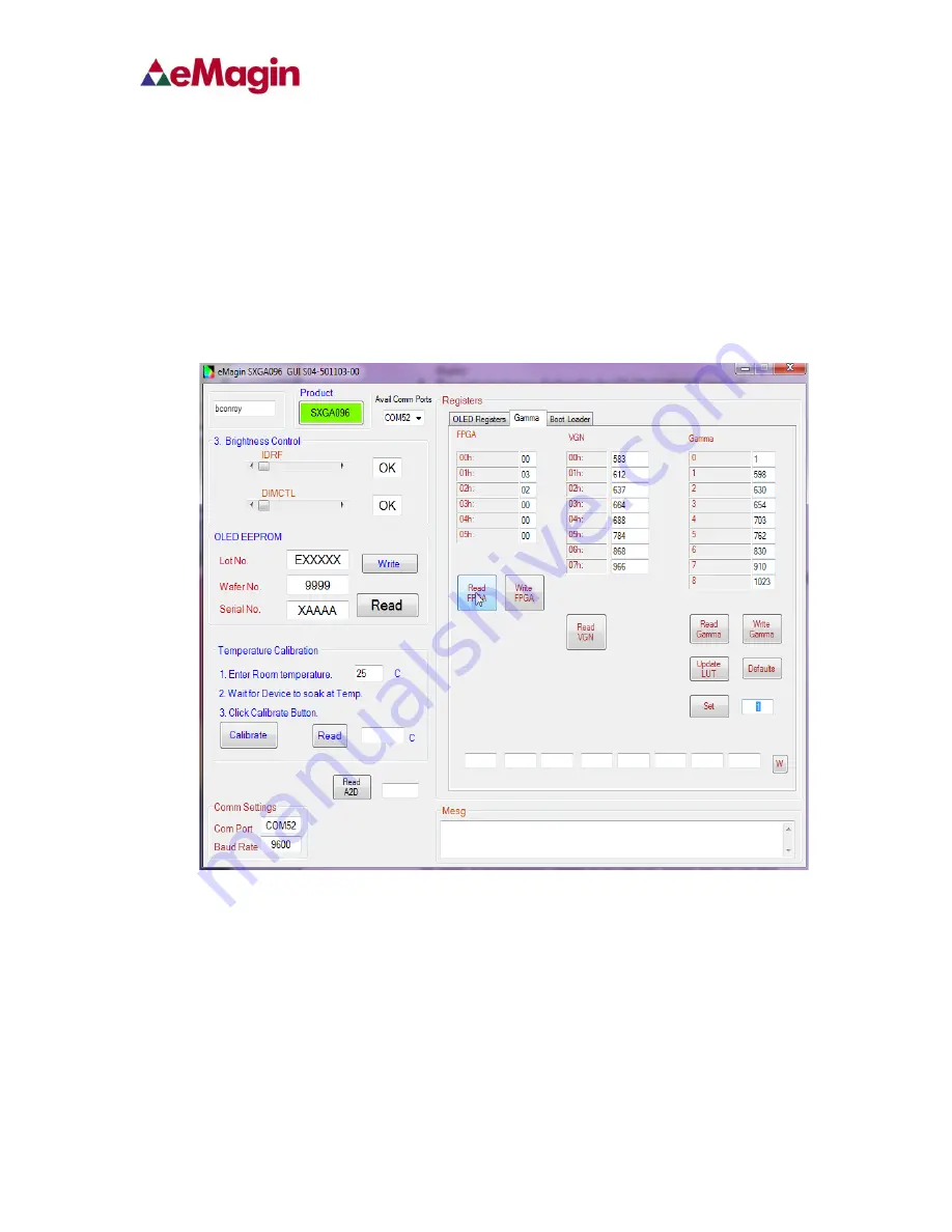
There are multiple ways to set the Gamma using the windows software. The Gamma
section of the software is shown below.
Figure 6-5 Gamma Section of the Software
7.6.1. Gamma Coefficients GC(0-8)
The 9 boxes in the Gamma section represent the 9 segment piece-wise-linear
function that defines the gamma curve. These 9 values are used to calculate the
256 element
look-up-table (LUT) that is required to transform input video data into a
gamma-corrected data signal for the microdisplay input port. The “Read” button will
retrieve the current 9 values from the microcontroller. The user can change any of the 9
values and see the resulting gamma corrected video by pressing the “Write” button.


