background image

  NTU-52V/VC. User manual (user)

12

Table 4 – Description of the connectors and controls on the rear panel

#

Rear panel element

Description

1

On/Off

Power button

2

12V

Power adapter connector

3

F

A functional key that reboots the device and resets it to factory settings

4

TV

RF port for connecting a coaxial cable

5

LAN 10/100

RJ-45 port for network devices connection (Ethernet/Fast Ethernet)

6

LAN 10/100/1000

RJ-45 port for network devices connection (Gigabit Ethernet)

7

Phone

RJ-11 connector for analogue phone connection

8

PON

SC port (socket) for PON with GPON interface

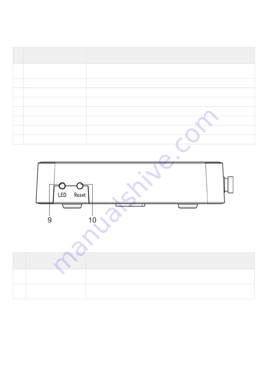
The side panel layout of the NTU-52V is depicted in figure below.

Figure 4 — NTU-52V side panel layout

See 

Table 5

 for detailed information about buttons located on the side panel of the device.

Table 5 – Description of the side panel LED indicators

#

Side panel element

Description

1

LED

LED on/off button

2

Reset/restore

A functional key that reboots the device and resets it to factory settings

Summary of Contents for NTU-52V

Page 1: ...IP address 192 168 1 1 Username user Password user Optical network terminals User manual Firmware version 1 2 1 ...

Page 2: ...n 25 5 3 1 The DHCP Setting submenu DHCP configuration 25 5 3 2 The Dynamic DNS submenu Dynamic DNS Configuration 26 5 3 3 The Firewall submenu Firewall configuration 27 5 3 4 The UPnP submenu Automated Setup of Network Devices 32 5 3 5 The RIP submenu Dynamic routing configuration 32 5 3 6 The Samba submenu Configuration of Samba users 33 5 4 The Advance menu Advanced settings 34 5 4 1 The ARP Ta...

Page 3: ...assword submenu Access control configuration setting passwords 43 5 6 5 The Firmware upgrade submenu Software Update 44 5 6 6 The Remote Access submenu Remote access rules configuration 44 5 6 7 The Time zone submenu System time configuration 45 5 7 The Statistics menu Traffic flow information for device ports 46 5 7 1 The Interface submenu Information about timers and errors 46 5 7 2 Th PON subme...

Page 4: ...s used to connect a PON network with data communication networks of a higher level ONT device is designed to connect user terminal equipment to broadband access services It can be used in residential areas and office buildings The range of ONT NTU equipment produced by ELTEX comprises of terminals with two UNI interfaces of 10 100 1000Base T and supports for FXS USB1 RF2 interfaces NTU 52V NTU 52V...

Page 5: ...Cs from DoS and virus attacks with the help of firewall and filter packets to control access based on ports and MAC IP addresses of source and target Users can configure a home or office web site by adding a LAN port into DMZ The Parental Control feature provides filtering of Web sites with inappropriate content domain blocking Virtual private network VPN provides mobile users and branch offices w...

Page 6: ...nal adapter for 220V 12V power supply Network functions bridge or router operation mode PPPoE auto PAP CHAP MSCHAP authorization IPoE DHCP client and static static IP address and DHCP DHCP client on WAN side DHCP server on LAN side DNS Domain Name System DynDNS Dynamic DNS UPnP Universal Plug and Play IPsec IP Security NAT Network Address Translation Firewall NTP Network Time Protocol QoS IGMP sno...

Page 7: ...nual user 7 Remote monitoring configuration and setup TR 069 Web interface OMCI CaTV1 1 Only for NTU 52VC The figures below illustrate applications schemes of NTU 52V VC Figure 1 NTU 52V and NTU 52VC application diagram ...

Page 8: ... 10Base T Ethernet IEEE 802 3u 100Base TX Fast Ethernet IEEE 802 3ab 1000Base T Gigabit Ethernet IEEE 802 3x Flow Control IEEE 802 3 NWay auto negotiation PON interface parameters Number of interfaces 1 Standards ITU T G 984 x Gigabit capable passive optical networks GPON ITU T G 988 ONU management and control interface OMCI specification IEEE 802 1Q Tagged VLAN IEEE 802 1P Priority Queues IEEE 80...

Page 9: ...ream connection speed 2488 Mbps Receiver sensitivity from 8 to 28 BER 1 0x10 10 Receiver optical congestion 4 dBm Subscriber analogue ports parameters Number of ports NTU 52V NTU 52VC 1 1 Loop resistance Up to 2 kΩ Call reception Pulse frequency DTMF Caller ID display Yes Control Local control Web interface Remote control Telnet TR 069 OMCI Firmware update OMCI TR 069 HTTP Acces restriction By pas...

Page 10: ...rs Model NTU 52V NTU 52VC Power supply 12 VDC 220 VAC power adapter 12 VDC 220 VAC power adapter RF port 1 Max power consumption 10 W Operating temperature From 5 to 40 С Relative humidity 80 max Dimensions 147 110 24 mm 160 120 40 mm Weight 0 3 kg ...

Page 11: ...of the connectors and controls on the rear panel Rear panel element Description 1 PON SC port socket for PON with GPON interface 2 Phone RJ 45 connector for analogue phone connection 3 LAN 10 100 RJ 45 port for network devices connection Ethernet Fast Ethernet 4 LAN 10 100 1000 RJ 45 port for network devices connection Gigabit Ethernet 5 USB Connector for external drives and other USB devices 6 12...

Page 12: ...thernet 6 LAN 10 100 1000 RJ 45 port for network devices connection Gigabit Ethernet 7 Phone RJ 11 connector for analogue phone connection 8 PON SC port socket for PON with GPON interface The side panel layout of the NTU 52V is depicted in figure below Figure 4 NTU 52V side panel layout See Table 5 for detailed information about buttons located on the side panel of the device Table 5 Description o...

Page 13: ... the NTU 52V is depicted in Fig 5 the front panel layout is depicted in Fig 6 Figure 5 NTU 52V top panel layout Figure 6 NTU 52V front panel layout The LED indicators located on the top and front panels show the current device status Table 6 lists possible statuses of the LEDs ...

Page 14: ...ed to OLT flashes green the device is in the registration process on OLT green the device is connected and registered on OLT 4 optical interface status indicator off the device is connected to OLT flashes red laser is off at LT side red there is no signal from OLT 5 Internet status indicator off there is no active connection to Internet green the device is ready connection established flashes gree...

Page 15: ...ashes green orange rapidly data transfer is in progress 10 USB port operation indicator off USB device is not connected green USB device is connected flashes green data transfer is in progress The front panel layout of the NTU 52VC is depicted in Figure 7 Figure 7 NTU 52VC front panel layout The LED indicators located on the front panel show the current state of the device Table 7 provides possibl...

Page 16: ...ta transfer is in progress 4 TV operation status indicator off RF port is disabled orange CaTV signal power is in the range from 10 dBm 8 dBm or 2 dBm 3 dBm green 8dBm CaTV signal power 2dBm 5 optical interface activity indicator off device is rebooting flashes red the device is not connected to OLT flashes green the device is in the registration process on OLT green the device is connected and re...

Page 17: ...ice press the Reset button located on its side panel In order to reset the device to the factory settings press the Reset button and hold it for 7 10 seconds until the indicator glows red and all other LEDs go out Factory settings for IP address are LAN 192 168 1 1 subnet mask 255 255 255 0 Access can be provided from LAN 1 and LAN 2 3 2 Delivery Package The NTU 52V VC standard delivery package in...

Page 18: ...tion of PC STB or other network devices They are logically included into br0 block FXS0 block is a port with RJ 11 connectors for connection of analogue phone It is logically included into the Voice block The Voice block can be controlled through web interface or remotely with ACS server via TR 069 standard The block specifies VoIP service parameters SIP server address phone number VAS etc Filter ...

Page 19: ...nnected username and password request page will be shown in the browser window 3 Enter your username into User Name and password into Password field 4 Click the Login button In the browser window the home page of the device s web interface will open Password changing To prevent unauthorized access to device in the future it is recommended to change password To change the password enter the new pas...

Page 20: ... the web interface General view of the device configuration window is depicted below The user interface window can be divided into 3 parts The navigation tree on the device settings menu The main settings window for the selected section User change button ...

Page 21: ...er device serial number PON Serial device serial number in the PON network Base WAN MAC WAN MAC address of the device Hardware Version hardware version Uptime device uptime Date Time current time on the device Image 1 Firmware Version Active current firmware version Image 2 Firmware Version backup firmware version CPU Usage CPU utilization percent Memory Usage memory utilization percent Name Serve...

Page 22: ...way gateway Status interface status Click the Refresh button to update the page 5 1 2 The IPv6 Status submenu Information about IPv6 system The tab displays the current status of IPv6 system Status IPv6 LAN Configuration IPv6 Address IPv6 address IPv6 Link Local Address local IPv6 address Prefix Delegation Prefix IPv6 address prefix WAN Configuration Interface interface name VLAN ID interface VLAN...

Page 23: ... PON PON Status Vendor Name manufacturer name Part Number part number Temperature current temperature Voltage voltage Tx Power transmission signal power Rx Power reception signal power Bias Current bias current Video Power video signal power PON Status ONU State ONU status ONU ID ONU ID LOID Status LOID status Click the Refresh button to update the page ...

Page 24: ...ss Mode access to the device via IPv6 address Auto when checked the access to the device via IPv6 address will be granted automatically Manual when checked you need to specify the IPv6 address manually IPv6 Address IPv6 address IPv6 Prefix Length length of the IPv6 address IP Version IP protocol version used IPv4 or IPv4 IPv6 Firewall Enabled Disabled enable disable firewall for LAN interface IGMP...

Page 25: ...in DHCP repeater mode IP Pool Range range of addresses distributed among clients Show Client button to view clients who leased the addresses When clicking a table with information about DHCP clients leased by a DHCP server is displayed Subnet Mask subnet mask Max Lease Time maximum lease time 1 for endless lease DomainName domain name Gateway Address gateway address DNS option defines DNS operatio...

Page 26: ... a constant domain name to a device computer router e g NTU 52V VC having a dynamic IP address The IP address can be assigned by IPCP in PPP connections or in DHCP Dynamic DNS is frequently used in local networks where clients are obtaining IP addresses through DHCP and then are registering their names on a local DNS server Services DNS Dynamic DNS Enable when selected enable DHCP server IP addres...

Page 27: ...ss filtering The IP Filtering function filters router traffic by IP addresses and ports Using these filters can be useful to protect or restrict the local network Services Firewall IP Port Filtering Default action Incoming Default Action Deny Allow filtering for incoming packets Outgoing Default Action Deny Allow filtering for outgoing packets To save the changes click the Apply Changes button To ...

Page 28: ...c to be forwarded or blocked depending on source and destination MAC addresses To change the mode click the Apply Changes button Services Firewall MAC Filtering Default Action default settings Deny when checked traffic pass is prohibited by default Allow when checked traffic pass is allowed by default MAC Address MAC address for which limitation access should be imposed Added filters are displayed...

Page 29: ...orwarding is performed Local port from to specify the range of local device ports for forwarding Protocol select protocol TCP UDP or both Remote port from to specify the initial port of incoming connection The Remote port to field will be filled automatically Interface select interface NAT loopback NAT loop allows transferring queries from LAN to the router thus for example you can check the work ...

Page 30: ...on 5 3 3 5 The Domain Blocking submenu Domain blocking configuration This section is used to set domain blocking Services Firewall Domain blocking To block the domain check Enable fill the Domain field and click the Add button Domain Blocking Enable Disable enable disable blocking Domain domain name To save the changes click the Apply Changes button All blocked domains are listed in the Domain Blo...

Page 31: ...g 5 3 3 7 The DMZ submenu Demilitarized Zone configuration When an IP address is set in the DMZ host IP address field all requests from external network that do not satisfy the Port Forwarding rules will be redirected to a DMZ host a trusted host with the specified address in the local network Services Firewall DMZ DMZ Host Enable Disable enable disable the host DMZ Host IP Address IP address To s...

Page 32: ...Dynamic routing configuration This section is used to select the interfaces on your device is that use RIP and the version of the protocol used Enable the RIP if you are using this device as a RIP enabled Device to communicate with others using the Routing Information Protocol Services RIP RIP Enable Disable enable disable the use of dynamic routing protocol RIP To accept and save the settings cli...

Page 33: ...mba submenu Configuration of Samba users In this submenu you can configure Samba users Services Samba Samba Samba Enable Disable enable disable Samba configuration Server String server name In the Accounts section you can create personal Samba accounts Services Samba Accounts Username account name New password password Confirmed Password password confirmation The Shares section is used to add Samb...

Page 34: ...g hardware addresses Every record created in the cache is stored for 5 minutes Advance ARP table IP Address IP address of the client MAC Address МАС address of the client To update the information click the Refresh button 5 4 2 The Bridging submenu Bridging parameters configuration In this section you can configure bridge parameters Here you can configure aging time of addresses in MAC table as we...

Page 35: ... 5 4 3 The Routing submenu Routing configuration This submenu is used to configure static routing Advance Routing To add the static route check Enable fill the corresponding fields and click Add Route Enable flag for route adding Destination destination address Subnet Mask subnet mask Next Hop next host Metric metric Interface interface Added static routes are displayed in the Static Route Table T...

Page 36: ...to close the table click Close 5 4 4 The Bridging grouping submenu Interface grouping In this section you can group the interfaces By default all interfaces are in the same group To place an interface to a new group you should Select a new group from the list below Select interfaces from the Available Interface list Click the arrow to transfer the interfaces into the group Apply the actions by cli...

Page 37: ...e To save the changes click the Apply Changes button 5 4 6 The IPv6 submenu IPv6 configuration In this section you can enable disable IPv6 operation For this you should check Enable Disable Advance IPv6 IPv6 To save the changes click the Apply Changes button 5 4 6 1 The RADVD submenu RADVD configuration In this submenu you can configure RADVD Router Advertisement Daemon Advance IPv6 RADVD MaxRtrAd...

Page 38: ... Mode select mode NONE operation without DHCP server DHCPRelay DHCP repeater operation mode DHCPServer Manual manual configuration of DHCP server DHCPServer Auto DHCP server auto provisioning To save the changes click the Apply Changes button After clicking on the Show Client button a table of active DHCPv6 server IP addresses will be displayed Advance IPv6 DHCPv6 Show Client 5 4 6 3 The MLD proxy...

Page 39: ...tatic IPv6 routes Advance IPv6 IPv6 routing Enable flag for route adding Destination destination address Next Hop next host Metric metric Interface interface To add IPv6 Routing fill in the appropriate fields and click the Add Route button Added routes are displayed in the Static IPv6 Route Table to update the information click the Update button To delete the whole table click the Delete All butto...

Page 40: ...terface through which the specified route is available To update the table click Refresh to close it click Close 5 4 6 6 The IPv6 IP Port filtering submenu Packet filtering configuration Use this page to configure the filtering of data packets transmitted through the gateway Advance IPv6 IP Port filtering Default Action default action Deny when checked traffic pass is prohibited by default ...

Page 41: ...e table click the Delete All button To delete one filter select it and click the Delete Selected button 5 5 The Diagnostics menu 5 5 1 The Ping submenu Checking the Availability of Network Devices Use this menu to test the availability of network devices with Ping utility Diagnostics Ping To test the availability of the connected device enter its IP address into the Host Address field and click th...

Page 42: ...dmin Settings Update Settings In this section you can restore settings from a file that was previously saved Update Settings with the Restore button Admin Settings Restore Default In this section you can reset the current settings to the factory default settings Restore Default click the Reset Settings to Default button 5 6 2 The Commit Reboot submenu Saving changes and rebooting the device Click ...

Page 43: ...ontrol configuration setting passwords In this section you can change a password to access the device Admin Password To change the password you must enter the existing password in the Old Password field then the new password in New Password and confirm it with Confirmed Password To confirm and save changes click the Apply changes button Click the Reset button to reset the value ...

Page 44: ...emote Access submenu Remote access rules configuration In this section you can configure remote access rules via HTTP Telnet ICMP protocols Admin Remote Access Enable enabling the rule to add Service selection of the protocol used Interface interface to which the rule applies IP Address source IP adress Do not switch off or reboot the device during the update The process may take several minutes T...

Page 45: ...ete Selected button 5 6 7 The Time zone submenu System time configuration In this section you can configure the device system time Synchronization with accurate online time servers is available Admin Time zone Current time current time Time Zone Select timezone Enable Daylight Saving Time enable daylight saving time Enable SNTP Client Update enable time synchronization via SNMP WAN Interface inter...

Page 46: ...rface submenu Information about timers and errors This section displays timers errors for packets for each interface Statistics Interface Interface interface Rx pkt packets received RX err errors on receive Rx drop rejected on receive Tx pkt packets sent Tx err transmission error Tx drop rejected on transmission ...

Page 47: ...nsmitted Packets Received packets received Unicast Packet Sent Unicast packets transmitted Unicast Packet Received Unicast packets received Multicast Packets Sent Multicast packets transmitted Multicast Packets Received Multicast packets received Broadcast Packet Sent Broadcast packets transmitted Broadcast Packet Received Broadcast packets received FEC Errors FEC errors Packets Dropped packets re...

Page 48: ...NTU 52V VC User manual user 48 6 The list of changes Document version Suitable firmware version Issue date Revisions Version 1 0 1 2 1 01 2020 First issue ...

Reviews: