Chapter 5
Installation
Fuel System
Attention: These instructions are intended for general guidance only. Consult
the current regulations in your area or the latest standards, NFPA 58 for the
United States or CAN/CGA 149.2 for Canada, for exact requirements.
Before you begin mounting any components, it is recommended that you determine the
approximate mounting location of all components to ensure that all parts can be connected with
the available lengths of hose and tubing. The recommended order of installation is:
1) Install the propane tanks or propane tank carriers.
All propane tanks must be “DOT” or “ASME” approved, setup for vapor withdrawal,and
mounted in line with the manufacturer's instructions and the applicable code.
Install the propane tank or propane tank carrier, such as the X-1025 or X-1050, following
the instructions included with product. Installation instructions are available for all tanks
purchased from Elston Manufacturing. If your tank or tank carrier does not have
instruction, contact the manufacturer for guidance and refer to the installation code that
applies in your area.
Any tanks should be mounted at least 18” from any portion of the exhaust system for the
heater or the vehicle. If this is not possible, it must be shielded from the exhaust
components by a vehicle frame member or a baffle of noncombustible material. The item
that is shielding the tank must have an air space between itself and the exhaust
component and itself and the tank to properly shield the tank from heat. If a baffle is
used, it should be constructed so that it is expected to resist corrosion at least as long as
the tank.
Attention: New tanks that are purchased empty come filled with air or an inert
gas that needs to be purged before the tanks are filled for the first time.
Remember to inform the propane supplier if your empty tank is new.
2) Mount the regulators
All regulators must be CSA/UL approved and securely attached with the vent opening
facing straight down. It should be mounted on exterior surface and must not be installed
in the space that the heater will be heating. It must be attached so it is supported by
screws attached to the mounting holes on the regulator and not by the fittings attached to
it. If the regulator is mounted in an unsheltered location, it must have either a durable
14
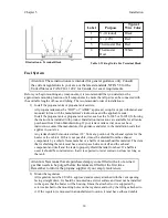
Label
Purpose
Typical
Wire Color
1
V- (Ground)
Black
2
V+ (12V)
Red
3
Thermostat Hot
Red
4
Thermostat
Heat
White
Table 1: Wiring Guide For Terminal Block
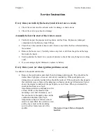
Illustration 6: Terminal Block


