Elster Eclipse AirHeat AH Operating Instructions Manual Download Page 6

6

AirHeat, V1, Operating Instructions, Edition 09.12
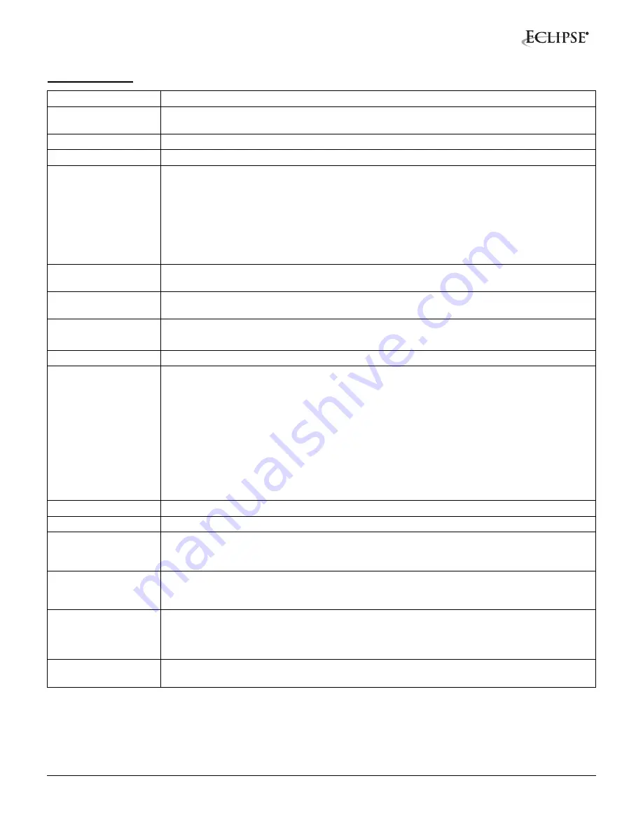
Specifications

*Based on blower motor limitations.
**Based on parallel air flow. If mounted in a cross flow, the flame will be shorter

Input

1,000,000 Btu/h per lineal foot (962 kW/m).

Fuels

Natural gas or 100% propane vapor. Call Eclipse for information on using other fuels. See 

Table 1 below.

Gas Turndown

40:1

Pilot Input 

Approximately 25,000 Btu/h (7.3 kW)

Gas Inlet Pressure

800,000 Btu/h/ft (769 kW/m)

Natural Gas: 2.2 ”w.c. (5.5 mbar)
Propane: 0.9 ”w.c. (2.2 mbar)

1,000,000 Btu/h/ft (962 kW/m)

Natural Gas: 3.5 ”w.c. (8.7 mbar)
Propane: 1.3 ”w.c. (3.2 mbar)

Gas pressure shown is a differential measured between the gas inlet and a tap on the duct 

wall, 10” to 20” (250 to 500 mm) downstream of the burner.

Ambient Temperature 

Limits*

-40° to +104°F (-40° to + 40°C)

Downstream 

Temperature Limits

1500°F (815°C)

Flame Length**

800,000 Btu/h/ft (769 kW/m): 2.3 ft (0.71 m)

1,000,000 Btu/h/ft (962 kW/m): 3.8 ft (1.17 m)

Piloting

Integral spark-ignited pilot; ignited plug included.

Flame Monitoring

Flame rod supplied. UV scanner adapters are available. For UV scanners, Eclipse 

recommends a flame monitoring system that terminates the ignition spark and proves the 

pilot flame without spark prior to opening the main gas valves. 

CGA requires two flame rods on burners over 3 ft (0.9 m) long. Use a flame monitoring 

endplate (Datasheet 140-5) to mount a second flame rod on the end opposite the gas inlet.

All burners where the flame must travel over 10’ must have flame supervision at both ends. 

One device must be at the pilot end while the other device must be at the furthest point from 

the pilot.

Motor

Standard: 230/460/3/60 TEFC. Other motors can be supplied.

Materials

All portions of the burner exposed to the flame are cast iron or 321 stainless steel.

Emissions

Emissions performance depends not only on the burner, but also on other factors such as 

chamber temperature, chamber design, and heat loading. For estimates of emissions 

performance in your application, contact Eclipse.

Packaging Options

Available with complete valve trains and control systems. AH burners and systems can be 

supplied already mounted on duct sections as specified by the customer. Contact Eclipse for 

information on custom packaged systems.

Models

   AH     Line-shape, blower mounted on rear      Datasheet 140-1
 TAH     “I”-shape, blower mounted on rear         Datasheet 140-3
CAH     Cross-shape, blower mounted on rear   Datasheet 140-4

Related Documents

For more information on AirHeat accessories such as blower and motor specifications, see 

Datasheet 140-5

Summary of Contents for Eclipse AirHeat AH

Page 1: ...Eclipse AirHeat Burners Model AH TAH CAH Version 1 Operating Instructions Edition 09 12 AH Front View Datasheet 140 1 AH Back View Datasheet 140 1 TAH Datasheet 140 3 CAH Datasheet 140 4 ...

Page 2: ... and Eclipse will not be liable for any other injury loss damage or expenses whether direct or consequential including but not limited to loss of use income or damage to material arising in connection with the sale installation use of inability to use or the repair or replacement of Eclipse s products Any operation expressly prohibited in this manual any adjustment or assembly procedures not recom...

Page 3: ...4 Capabilities 4 Operator Training 4 Replacement Parts 4 Information Guide 5 Burner Operating Parameters Requirements 5 Specifications 6 Control System Requirements 7 Approval of Components 8 Duct Design and Burner Mounting 8 Startup and Adjustment 10 Rountine Maintenance 11 Troubleshooting 12 ...

Page 4: ...s wear the appropriate protective equipment when approaching the burner This manual provides information regarding the use of these burners for their specific design purpose Do not deviate from any instructions or application limits described herein without written approval from Eclipse Capabilities Only qualified personnel with sufficient mechanical aptitude and experience with combustion equipme...

Page 5: ...ough 140 5 Burner Environment Weather Protection Protect burners from the weather Combustion Air Must be free of contaminants Eclipse strongly recommends use of a combustion air filter to remove airborne particles If corrosive fumes or materials are present in the air supply the blower with fresh clean air from an uncontaminated area of the plant Room Openings If the burner is mounted on the side ...

Page 6: ...proves the pilot flame without spark prior to opening the main gas valves CGA requires two flame rods on burners over 3 ft 0 9 m long Use a flame monitoring endplate Datasheet 140 5 to mount a second flame rod on the end opposite the gas inlet All burners where the flame must travel over 10 must have flame supervision at both ends One device must be at the pilot end while the other device must be ...

Page 7: ...he burner See Figure 1 Figure 1 Check Valve Operation Do not install any valve or controlling device in the gas line between the burner and the check valve tee Because this section of the gas line carries a partial premix at low fire it is possible under unusual conditions for the flame to travel back through the pipe to the tee Devices installed in this section may be damaged and may melt releasi...

Page 8: ...tandards such as NFPA Standard 54 ANSI Z223 EN 746 2 Where to Get the Standards The NFPA Standards are available from National Fire Protection Agency Batterymarch Park Quincy MA 02269 www nfpa org The ANSI Standards are available from American National Standard Institute 1430 Broadway New York NY 10018 www ansi org Duct Design and Burner Mounting Duct Design See Figure 3 for typical mounting arran...

Page 9: ...to 1200 fpm 2 5 to 6 1 m s Min Max Velocity 500 to 1200 fpm 2 5 to 6 1 m s Sealed Duct Press 0 2 to 0 5 w c 0 5 to 1 2 mbar Min Max Velocity 500 to 1200 fpm 2 5 to 6 1 m s Slot Fired Duct Press 0 to 0 5 w c 0 to 1 2 mbar Min Max Velocity 500 to 1200 fpm 2 5 to 6 1 m s Min Max Velocity 500 to 6000 fpm 2 5 to 30 m s 1000 to 4000 fpm 5 0 to 20 m s Optimum Velocity Guidelines for All Mounting Arrangem...

Page 10: ...ntil the air pressure drop is between 0 4 w c 1 mbar minimum and 1 0 w c 2 5 mbar maximum For a given input lower air pressure drops will produce a longer flame and higher drops will produce a shorter flame Large Burners Only Some models such as the 640 680 and 720 TAH burners contain a butterfly valve in the check valve line On these models after setting the air flow as described in the previous ...

Page 11: ...ngth for a given gas input increase the air pressure drop as described in Set Air Pressure Drop paragraph above Check All Settings Return the burner to low fire and check to ensure the burner remains lit with a stable flame that extends down the burner length Cycle the burner between low and high fire several times checking pressure drops and flame lengths Routine Maintenance Motor Lubrication Oil...

Page 12: ...as flow Flame failure when main burner returns from high to low fire Gas pressure to pilot regulator Under gassing pilot Check pilot gas pressure to regulator should be 1 PSIG 70 mbar maximum Check pilot regulator inlet and outlet gas pressures Check pilot flame Check impulse line for possible dirt clogging Check impulse line duct connection for effective pressure being transmitted to regulator Re...

Page 13: ...Notes i ...

Page 14: ... Eclipse Inc All Rights Reserved ...

Reviews: