

Display Corlo Touch KNX
2
Display Corlo Touch KNX
• Version: 25.04.2018 • Technical changes and errors excepted. • Elsner Elektronik GmbH • Sohlengrund 16 • 75395 Ostelsheim • Germany • www.elsner-elektronik.de •
Technical Service: +49 (0) 7033 / 30945-250
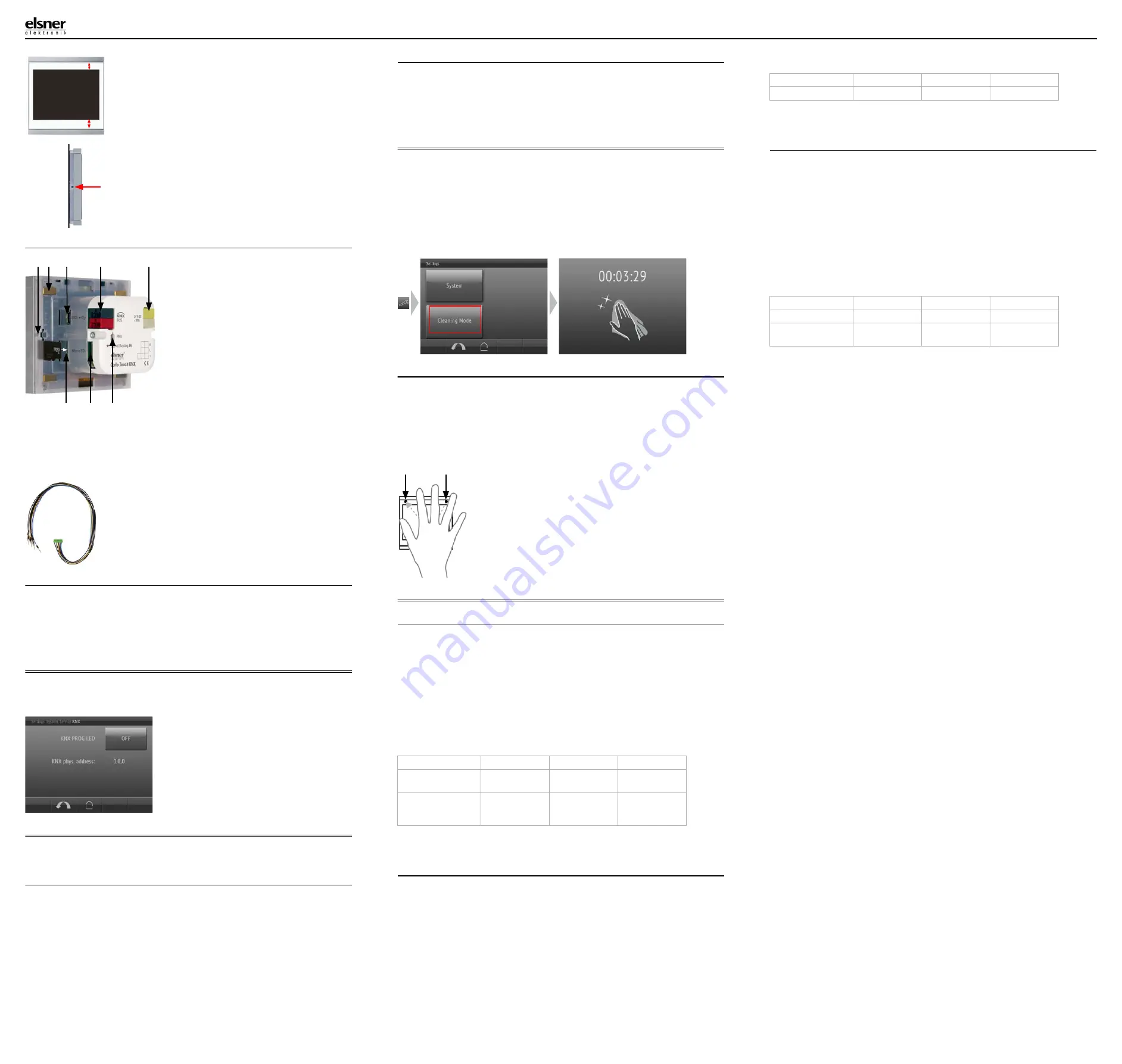
2.2.3. Connection overview
Connect the bus voltage (no. 4, red/black terminals) and auxiliary voltage (no. 5,
yellow/white terminals). Use the attached breakout cable for connecting the digital/
analog inputs (no. 7). The cables for the inputs can be extendet to up to 10 m. All
GND connections of the inputs are bridged internally (black cable).
2.3. Instructions for assembly and operational start-up
Never expose the sensor to water (e.g. rain) or dust. This can damage the electro-
nics. You must not exceed a relative air humidity of 95%. Avoid condensation.
After the operating voltage has been applied, the device will enter an initialisation
phase lasting a few seconds. During this phase no information can be received or
sent via the bus.
3.
Addressing the device
The programming mode for addressing at the bus is activated via the program-
ming button at the back of the housing or via the display.
Settings > System > Service > KNX
4.
Setting up the WLAN connection
Only for the
Corlo Touch KNX WL
model with an interface for wireless network
connection!
4.1. WLAN settings in the ETS
The WLAN connection must be set up in the ETS. Consult the WLAN setting section
in the manual
ETS:System Settings > WLAN
2.13.1 WLAN
You set the network name and the encryption for compatibility with the WLAN net-
work access point. The IP address allocation can be made either automatically by
DHCP or manually.
4.2. Displaying WLAN status on the display
You can call up information on the current status of the connection on the
Corlo
Touch KNX
display. Network name, signal strength, IP address, DNS address and
GW address are displayed.
Settings > System > Service > WLAN Status
3.11.7. WLAN Status
5.
Maintenance and care
Fingerprints on the glass area and frame are best removed with a cloth moistened
with water or a microfiber cloth. Do not use an abrasive cleaning agent or aggres-
sive cleansing agents.
For cleaning of the screen, the „cleaning mode“ can be used, that is activeted via
the display.
Settings > Cleaning Mode
During a period set in the ETS, the touch function is disabled then and the screen
can be cleaned.
6.
Use of the proximity sensor
With the integrated proximity sensor, the screen saver can be deactivated already
when a hand aproaches (fast activation from stand-by) or functions can be trigge-
red via the bus (switching on approach).
To use the proximity sensor for sending communication objects, for example for
switching, set the proximity sensor parameters in the ETS accordingly. See manual
chapter
2.7. Proximity sensor
7.
Load individual images
7.1. Images for screensaver
The setting of the screen saver is described in the manual chapters
2.4. Display (ETS) and 3.4.4. Screen saver (Display)
Images that are shown as the screensaver must be stored on a micro SD card. In
order that the system can recognize the SD card, carry out a reset in the menu after
inserting it
Settings> System > Reset
This is not
necessary
if the card was inserted before booting the system. The card
must remain in the device.
Store images in the given size in a corresponding folder on the top level of the SD
card:
Images for individual image display ("diafix" folder) must have a 4-digit numerical
sequence so that they can be called up in the ETS and in the menu (0001...9999).
7.2. Images for image display
Images can be called up as a stationary display (e. g. welcome screen). In contrast
to the screensaver, the touch function is disabled while a stationary image is dis-
played.
Images that are to be called up via the "Stationary Image" communication object
must be stored on a micro SD card. In order that the system can recognize the SD
card, carry out a reset in the menu after inserting it
Settings> System > Reset
This is not
necessary
if the card was inserted before booting the system. The card
must remain in the device.
Store images in the given size in a corresponding folder on the top level of the SD
card:
Stationary images must have a 4-digit numerical sequence so that they can be cal-
led up in the ETS and in the menu (0001...9999).
7.3. Exchanging images and graphics
For the
Corlo Touch KNX
display pages, a large number of icons from the area
of security, multimedia, sensors, operation, house, light and air conditioning and
drive control are available and these are stored in the device. However, you can
also use proprietary symbol graphics and rotary control graphics.
Images that are shown as icons must be stored on a micro SD card. In order that
the system can recognize the SD card, carry out a reset in the menu after inserting
it
Settings> System > Reset
This is not
necessary
if the card was inserted before booting the system. The card
must remain in the device.
Store images in the given size in a corresponding folder on the top level of the SD
card:
Icons must have a 4-digit numerical sequence so that they can be called up in the
ETS and in the menu (0001...9999).
Fig. 5
The display unit can now be put in place.
The wider part of the display edge must
be at the bottom.
The display unit engages on the right and left si-
des and is also held by magnets.
Fig. 6
To remove the display unit from the frame,
press one of the snaplock connections on the
side of the device with a pointed instrument.
You can now pull the device to the front at the
unlocked side und remove it.
Wall
Fig. 7
1 Snaplock connector seating
2 Magnets (additional fixing)
3 USB socket
4 KNX terminal bus +/-
5 Terminal auxiliary supply 24 V
DC ±10%, terminal configurati-
on independent from polarity
6 Micro SD socket (card contacts
must show in the direction of
the display when inserting it)
7 Analog/digital inputs socket
8 Programming button for ad-
dressing the device at the bus
(recessed)
2
3
4
5
1
6
7
8
Fig. 8
Breakout cable for analog/digital inputs:
Input 1: black/white
Input 2: black/yellow
Input 3: black/lilac
Input 4: black/blue
KNX programmming LED ON:
Programming mode active.
KNX programming LED OFF:
Programming mode off.
The current address is displayed (Ad-
dress 15.15.250 when delivered).
Image type
Resolution
File format
Folder name
Images for slide
show
320 × 240 pixels .jpg (RGB mode) slideshow
Images for
individual image
display
320 × 240 pixels .jpg (RGB mode) diafix
The proximity sensor reacts only when a larger ob-
ject moves from the front into the detection area. It
is best to move the flat hand towards the display so
that the sensor reacts quickly.
Fig. 9 Proximity sensor
1 Proximity sensor Sender
2 Proximity sensor Receiver (and light sensor for
adaption of the screen brightness)
2
1
Image type
Resolution
File format
Folder name
Stationary images
320 × 240 pixels .jpg (RGB mode) festbilder
Image type
Resolution
File format
Folder name
Symbol/small icon
48 × 48 pixels
.png
icons
Icons for rotary con-
trol
158 × 158 pixels .png
icons


