

Remote control Remo KNX RF
2
Remote control Remo KNX RF
• Version display 1.3.0, KNX application 2.0 • Version: 13.05.2020 • Technical changes and errors excepted. • Elsner Elektronik GmbH • Sohlengrund 16 • 75395 Ostelsheim • Germany • www.elsner-elektronik.de •
Technical Service: +49 (0) 7033 / 30945-250
3.3.3. Switching devices (on/off)
Tapping the right side of the bar switches the device on. Tapping the left
side of the bar switches the device off.
The buttons can be provided with a
label, in the ETS, in the menu Wireless channel configuration > On/Off text (see ma-
nual, Chapter Changing the On/Off Text).
If the ‘Feedback’ setting is activated in the ETS, the status reported by the bus (text,
on/yellow symbol or off/grey symbol) is displayed. Otherwise, there is no feedback
for the status. The feedback text can be changed in the ETS in the menu
Wireless
channel configuration > Feedback text
(see manual, Chapter
Changing the Feed-
back Text
).
For ETS settings,
see manual, Chapter
Channel 1...8
, section
Switching
.
3.3.4. Dimming
‘Buttons’ and ‘sliders’ can be activated as operating interfaces in the ETS. If mul-
tiple interfaces are active, you can switch between the views using the right area
of the bar (side symbol ).
Buttons:
A shorter tap
on
+ switches on
, tapping on
- switches off
.
A longer tap
on
+ adjusts the light to a brighter setting
, holding
-, to a dar-
ker setting.
If you release the key, the brightness stops changing.
The time interval between short and long and other parameters are set in the ETS.
If the ‘Feedback’ setting is activated in the ETS, the status reported by the bus (on/
yellow symbol or off/grey symbol) is displayed. Otherwise, there is no feedback for
the status.
The dimming percentage is shown in the button, left of the symbol, if the ‘Feed-
back’ setting was activated in the ETS.
Sliders:
Shift the point on the line to dim the lights.
If ‘feedback’ is activated in the
ETS, then the current brightness will be displayed in %, and the position of the
point on the line will correspond to the current brightness as soon as feedback is
received.
For ETS settings,
see manual, Chapter
Channel 1...8
, section
Dimming
.
3.3.5. RGB(W) lights
To set individual light values for red, green, blue and white, use the buttons to
switch the lights on/off, and three (RGB) or four (RGBW) sliders to adjust the co-
lour.
These functions can all be placed on a single channel (i.e. one bar). In this case, you
can switch between the functions using the right area of the bar (side symbol ).
However, the functions can be distributed over multiple channels, so that swit-
ching and colour control can be carried out via multiple adjacent bars. The confi-
guration takes place in the ETS.
Sending settings to the lights:
Depending on the settings, the changes on the RGBW sliders will be sent directly
to the lights, or the settings will only be sent if you remain on the right button (on)
longer.
On/off buttons:
Tapping the right side of the bar switches the device on.
Tapping the left
side of the bar switches the device off.
The buttons can be provided with a
label, in the ETS, in the menu
Wireless channel configuration > On/Off text
(see ma-
nual, Chapter
Changing the On/Off Text
).
If the ‘Feedback’ setting is activated in the ETS, the status reported by the bus (text)
is displayed. Otherwise, there is no feedback for the status. The feedback text can
be changed in the ETS in the menu
Wireless channel configuration > Feedback text
(see manual,
Chapter Changing the Feedback Text
).
Colour view:
The current colour setting is shown in a box on the bar; the representation on the
display can deviate severely from the actual light colour.
RGB luminaire without feedback: 1 box
RGBW luminaire without feedback: 2 boxes
RGB luminaire with feedback: 2 boxes
RGBW luminaire with feedback: 4 boxes
Sliders:
Shift the point on the line to change the light colour with the red, green,
blue and white parameters.
The colour bar on the left shows the colour; the re-
presentation on the display can deviate severely from the actual light colour.
If ‘feedback’ is activated in the ETS, then the current brightness will be displayed
in %, the position of the point on the line will correspond to the current brightness,
and the colour bar will update as soon as feedback is received.
For ETS settings,
see manual, Chapter
Channel 1...8
, section
RGBW
.
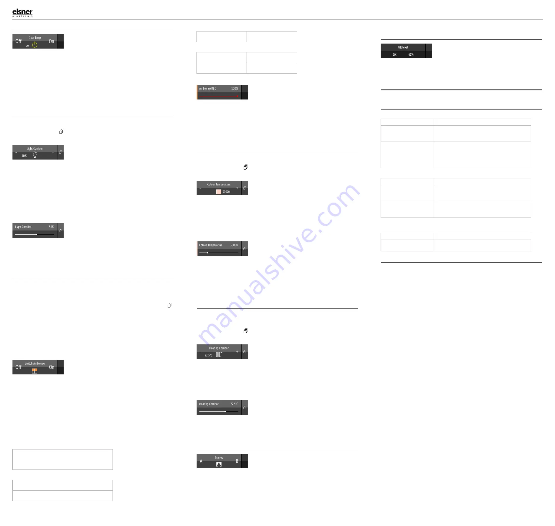
3.3.6. Lights with adjustable colour temperature
‘Buttons’ and ‘sliders’ can be activated as operating interfaces in the ETS. If mul-
tiple interfaces are active, you can switch between the views using the right area
of the bar (side symbol ).
Buttons:
H switches the device on
; holding
- switches the device off.
T makes the light colder
; tapping
-, warmer
.
The time interval between short and long and other parameters are set in the ETS.
If the ‘Feedback’ setting is activated in the ETS, the colour temperature value re-
ported by the bus (colour field red (warmer light), blue (colder light) and Kelvin va-
lue) is displayed. Otherwise, there is no feedback for the status.
Sliders:
Shift the point on the line to change the colour temperature.
If ‘feedback’
is activated in the ETS, then the current colour temperature will be displayed in Kel-
vins (K), and the position of the point on the line will correspond to the current co-
lour temperature as soon as feedback is received.
The colour bar on the right indicates the colour tendency towards warm or cold
with reddish, white or bluish colours.
For ETS settings,
see manual, Chapter
Channel 1...8
, section
Colour temperature
.
3.3.7. Changing temperature
Adjusting heating or cooling
‘Buttons’ and ‘sliders’ can be activated as operating interfaces in the ETS. If mul-
tiple interfaces are active, you can switch between the views using the right area
of the bar (side symbol ).
Buttons:
Tap+ to increase the target temperature
.
Tap- to reduce the target temperature
.
The current target temperature is shown in the button, left of the symbol, if the
‘Feedback’ setting was activated in the ETS (always for temperature objects). The
way the temperature change takes place is set in the ETS.
Sliders:
Shift the point on the line to change the temperature.
If ‘feedback’ is activa-
ted in the ETS, then the current target temperature will be displayed in C° as soon
as feedback is received.
For ETS settings,
see manual, Chapter
Channel 1...8
, section
Temperature
.
3.3.8. Scenes
Each scene button is used to control two scenes: The left button half for one, and
the right button half for the other scene.
Tap
a button half for a short time to
call the scene
.
Holding it longer
saves the scene
in the current state (e.g. movement position,
dimming level etc.), provided this function was activated in the ETS.
For ETS settings,
see manual, Chapter
Channel 1...8
, section
Scene
.
3.3.9. Measured value view
A bar can be used as a display area for values from the bus system. Actions not
possible.
For ETS settings,
see manual, Chapter
Channel 1...8
.
4.
Care and maintenance
Please carefully clean the remote control with a damp cloth. Do not use detergent.
4.1. Troubleshooting
Problem:
The display is off, the remote control does not react:
Problem:
The display is on, the device/drive does not react to button presses:
Problem:
Menu cannot be accessed (the menu does not appear if the upper bar is
swiped from the top downwards):
5.
Disposal
After use, the device must be disposed of or recycled in accordance with the legal
regulations. Do not dispose of it with the household waste!
set
RGB mixed value
set
RGB mixed value
set
white calue
RGB
feedback value
set
RGB mixed value
RGB
feedback value
set
RGB mixed value
white
feedback value
set
white value
Cause
Procedure
Transport block active
Please connect the remote control to the power
supply using a charging cable. This deactivates the
lock.
Battery not charged
Please connect the remote control to the power
supply using a charging cable to charge the bat-
tery. The charge status is shown with the battery
symbol at the top right corner of the operation
pages.
Cause
Procedure
Wireless contact has been
lost, transmitter is too far
away from the receiver
Choose another location
No voltage to receiver unit
or faulty receiver unit
Switch on the receiver unit (e.g. the control unit).
Should wireless contact still not be established,
please contact Customer Service
Cause
Procedure
Menu locked
Unlock the menu in the ETS application or via the
corresponding communication object