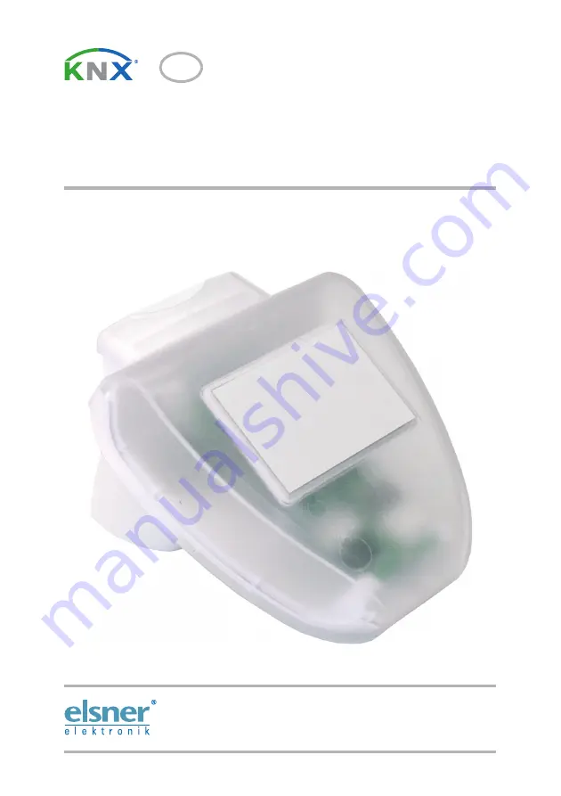
background image

KNX PY

Pyranometer

Technical specifications and installation instructions

Item number 70157

EN

Elsner Elektronik GmbH 

Control and Automation Engineering

Sohlengrund 16
D - 75395 Ostelsheim Phone +49 (0) 70 33 / 30 945-0

[email protected]

Germany

Fax

+49 (0) 70 33 / 30 945-20 www.elsner-elektronik.de

Summary of Contents for KNX PY

Page 1: ... installation instructions Item number 70157 EN Elsner Elektronik GmbH Control and Automation Engineering Sohlengrund 16 D 75395 Ostelsheim Phone 49 0 70 33 30 945 0 info elsner elektronik de Germany Fax 49 0 70 33 30 945 20 www elsner elektronik de ...

Page 2: ......

Page 3: ... the sensor 6 2 3 1 Attaching the mount 6 2 3 2 View of rear side and drill hole plan 7 2 3 3 Preparing the sensor 8 2 3 4 PCB layout 9 2 3 5 Mounting the sensor 9 2 4 Notes on mounting and commissioning 10 3 Addressing of the device at the bus 10 4 Maintenance 10 5 Transmission Protocol 11 5 1 List of all communication objects 11 6 Setting of parameters 13 6 1 General settings 13 6 2 Threshold va...

Page 4: ...leshooting of the device must only be carried out by a competent electrician Safety advice Safety advice for working on electrical connections components etc DANGER indicates an immediately hazardous situation which will lead to death or severe injuries if it is not avoided WARNING indicates a potentially hazardous situation which may lead to death or severe injuries if it is not avoided CAUTION i...

Page 5: ... be adjusted per parameter or via communication objects 2 AND and 2 OR logic gates with each 4 inputs Every switching incident as well as 8 logic inputs in the form of communication objects may be used as inputs for the logic gates The output of each gate may optionally be configured as 1 bit or 2 x 8 bits Configuration is made using the KNX software ETS The product file can be down loaded from th...

Page 6: ...e assumed that risk free operation is no longer guaranteed The device is only to be used for its intended purpose Any improper modification or failure to follow the operating instructions voids any and all warranty and guarantee claims After unpacking the device check it immediately for possible mechanical damage If it has been damaged in transport inform the supplier immediately The device may on...

Page 7: ...f clearance must be left all round the device Concurrently the prevents spray raindrops hitting the device or snow snow penetration from impairing the measurement It also does not allow birds to bite it Fig 1 There must be at least 60 cm of space below to the sides and in front of the sensor left from other elements structures construction parts etc 60 cm Fig 2 The sensor must be mounted onto a ve...

Page 8: ...red by adhesive strips to the rear side of the housing Fasten the mount vertically onto the wall or pole Fig 4 For installation in the northern hemisphere the sensor must be aligned to face south For installation in the southern hemisphere the sensor must be aligned to face north Nord Süd Fig 5 When wall mounting flat side on wall crescent shaped collar upward Collar Fig 6 When pole mounting curve...

Page 9: ... exem plary Example of the use of a mounting arm Due to flexible ball joints the sensor can be brought into ideal position Fig 8 Example use of the hinge arm mounting With the hinge arm mounting the weather sta tion projects from beneath the roof overhang Sun wind and precipitation can act upon the sensors without hindrance Fig 9 Example use of the hinge arm mounting Fitting to a pole with worm dr...

Page 10: ...ing the sensor The sensor cover snaps in on the left and right along the bottom edge see Fig Remove the cover Push the connection cable through the rubber seal on the bottom of the device and connect voltage and data cable to the provided clamps Fig 11 1 Cover snaps 2 Bottom part of housing 1 2 Unsnap cover and remove upwards ...

Page 11: ... housing by putting the cover back over the bottom part The cover must snap in on the left and right with a definite click Fig 12 1 KNX clamp 2 Programming LED 3 Programming pushbutton for the teach in of the device 1 2 3 Fig 13 Make sure the cover and bottom part are properly snapped together This picture is looking at the closed sensor from under neath Fastening ...

Page 12: ...with the bus address 15 15 250 You can program another ad dress into the ETS by overwriting the 15 15 250 address or by teaching via the pro gramming key on the circuit board inside the housing 4 Maintenance WARNING Risk of injury caused by components moved automatically The automatic control can start system components and place people in danger Always isolate the device from the mains for servic...

Page 13: ...t maximum value Input 1 006 C R W 6 Sensor malfunction Output 1 001 C R T 7 Threshold value 1 16 bit value Input Output 9 008 C R W T A 8 Threshold value 1 1 increment 0 decrement Input 1 006 C R W 9 Threshold value 1 Increment Input 1 006 C R W 10 Threshold value 1 Decrement Input 1 006 C R W 11 Threshold value 1 Switching output Output 1 006 C R T 12 Threshold value 1 Switching output block Inpu...

Page 14: ... Switching output block Input 1 006 C R W 31 Logic input 1 Input 1 001 C R W 32 Logic input 2 Input 1001 C R W 33 Logic input 3 Input 1001 C R W 34 Logic input 4 Input 1001 C R W 35 Logic input 5 Input 1001 C R W 36 Logic input 6 Input 1001 C R W 37 Logic input 7 Input 1001 C R W 38 Logic input 8 Input 1001 C R W 39 AND Logic 1 Switching output 1 001 C R T 40 AND Logic 1 8 bit output A 5 010 C R T...

Page 15: ...y From measurement value change of only if sending on change 1 50 5 Periodically transmit measured value all only if sending periodically 5 secs 2 h Use measurement value in kWh m No Yes Transmission behaviour as with measured value in W m Reset measurement value KWh m to 0 at sunrise on reception of a communication object Use maximum value No Yes Value is not retained after reset Use malfunction ...

Page 16: ...arameter Threshold value in W m 0 2500 500 Hysteresis of the threshold value in 0 50 20 Threshold value setting via Communication object The last communicated value shall be retai ned not after voltage restoration the changed threshold value can be safed at least 100 000 times after voltage restoration and programming Attention Do not use during initial start up Start threshold value in W m valid ...

Page 17: ...block on value 0 release on value 0 block on value 1 release Value of blocking object before 1 communication 0 1 Behaviour of switching output on block do not transmit message transmit 0 transmit 1 Behaviour of switching output on release if switching output 0 transmit 0 Use block of the switching output Yes No Use block of the switching output Yes Evaluation of the blocking object if value 1 bloc...

Page 18: ...8 bit objects Logic output sends one 1 bit object if logic 1 object value 1 0 if logic 0 object value 1 0 Communication object AND Logic 1 sends in case of the change of logic in case of the change of logic to 1 in case of the change of logic to 0 in case of the change of logic and cyclically in case of the change of logic to 1 and cyclically in case of the change of logic to 0 and cyclically send...

Page 19: ...object logic input 7 Communication object logic input 7 inverted Communication object logic input 8 Communication object logic input 8 inverted Threshold value 1 Threshold value1 inverted Threshold value 2 Threshold value 2 inverted Threshold value 3 Threshold value 3 inverted Threshold value 4 Threshold value 4 inverted Malfunction Malfunction inverted 6 3 3 OR Logic 1 2 Communication objects AND...

Page 20: ...those of the AND logic 6 3 4 Linkage inputs of OR Logic The linkage inputs of the OR logic correspond with the parameters of the AND logic The OR logic is additionally provided with the following inputs AND Logic output 1 AND Logic output 1 inverted AND Logic output 2 AND Logic output 2 inverted Logic output sends one 1 bit object two 8 bit objects ...

Page 21: ......

Page 22: ...mbH Control and Automation Engineering Sohlengrund 16 75395 Ostelsheim Phone 49 0 70 33 30 945 0 info elsner elektronik de Germany Fax 49 0 70 33 30 945 20 www elsner elektronik de Technical support 49 0 70 33 30 945 250 ...

Reviews: