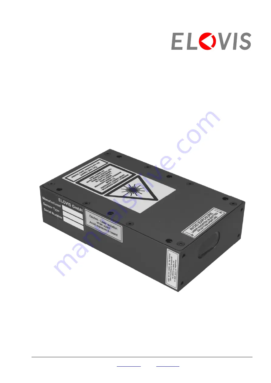
ELOVIS mSPEED smartsensor User Manual Download Page 1

User Manual


µ

SPEED 

smartsensor 

Optical Device for Speed and Length Measurement  

µSPEED-smart

-Sx and –

smart-ECO

-Sx 

Version 1.0


ELOVIS GmbH 

 Karl-Friedrich-Str. 14-18 

 D-76133 Karlsruhe 

 Tel.: +49 (0) 721 933823 0 

 Fax: +49 (0) 721 933823 23 

E-Mail: 

[email protected]


 Home: 

www.elovis.de


Summary of Contents for mSPEED smartsensor

Page 1: ...ptical Device for Speed and Length Measurement SPEED smart Sx and smart ECO Sx Version 1 0 ELOVIS GmbH Karl Friedrich Str 14 18 D 76133 Karlsruhe Tel 49 0 721 933823 0 Fax 49 0 721 933823 23 E Mail in...

Page 2: ...ations given in this instruction manual can result in dangerous irradiation from the laser Servicing of laser appliances should be performed by suitably qualified personal only The lasers used do not...

Page 3: ...iations is also harmless The complete characteristics of the SPEED measuring unit are given in chapter 3 1 1 Laser Type Used Maximum power 25 mW Wavelength 780 nm Laser class 3B Table 1 Laser Data Oth...

Page 4: ...nning on the day the equipment is ready to be shipped at our plant We promise to repair or replace at will as quickly and reasonably as possible any parts which are proven to be faulty in design mater...

Page 5: ...Interfaces 6 2 2 4 Configuration Alternatives 8 2 2 5 Pin Assignment 8 3 Laser Protection 11 3 1 SPEED smartsensor Laser Device 12 3 1 1 Characteristics 12 3 1 2 Saftey feature 12 3 2 Safety Measures...

Page 6: ...ELOVIS 1 Introduction 1 INTRODUCTION SPEED smartsensor Technical Data Scope of Delivery Installation and Commissioning ID308 1...

Page 7: ...g the product from a laser based measuring unit that projects a striated pattern on the object The measured object backscatters the laser beam into the measuring unit The frequency of the backscattere...

Page 8: ...e of 120mm 3mm to 5mm or 240 mm 10mm from the measured object see Figure 1 The rules and regulations of laser protection must be followed see chapter 3 Figure 1 Mounting tolerances and alignment of SP...

Page 9: ...off status and has to be connected additionally to one or more emergency shut off devices 4 Instead of 2 and 3 Connect the other end of the sensor cable with the optional ELOVIS Speed Box The possibi...

Page 10: ...2 Interfaces 2 INTERFACES The SPEED smartsensor is delivered with a connector plug which provides all signals and which is used for power supply in addition Mechanical Interface Electrical Interface I...

Page 11: ...pole standard Sub D 2 2 ELECTRICAL INTERFACE 2 2 1 VOLTAGE supply voltage 18 30V nominal 24V controlled wattage max 3W pin assignment see 2 2 5 2 2 2 EMERGENCY SHUT OFF LASER INTERLOCK type of signal...

Page 12: ...a combination thereof Interfaces which can be implemented are described in the following RS 485 Possible in configuration K3 K4 and K7 see 2 2 4 Interface to RS 485 min baud rate 1200 baud max baud ra...

Page 13: ...K2 K4 K8 and K9 one I O Port K7 two I O Ports K10 three I O Ports see 2 2 4 input to RS 422 input specification ouput to RS 422 output specification pin assingment see 2 2 5 2 2 4 CONFIGURATION ALTER...

Page 14: ...I O Table 3 Binder Flange Connector Pin Signal K1 K2 K3 K4 K5 K6 K7 K8 K9 K10 14 VCC X X X X X X X X X X 15 PGND X X X X X X X X X X 12 SGND X X X X X X X X X X 13 EmS off X X X X X X X X X X 8 Config...

Page 15: ...20 Ohm effectively Depending on the kind of mode the configuration interface is assigned as follows Pin Signal RS 232 Mode RS 485 Mode F Config A RS 232 TXD RS 485 E Config B RS 232 RXD RS 485 Table 5...

Page 16: ...VDE 0837 Radiation Safety of Laser Equipment Classification of Systems Requirements User Guidelines DIN VDE 0836 VDE regulations on Electrical Safety of Laser Equipment and Installations This chapter...

Page 17: ...g wire is also harmless Exposure even a direct one of the skin to the radiations is also harmless The SPEED smartsensor Laser Data are listed in the following Table 7 Laser class 3B Visible laser radi...

Page 18: ...esponsible for laser protection should be charged in writing to supervise the operation of the laser equipment 5 The employer s liability insurance association or the equivalent organization should be...

Page 19: ...ELOVIS 4 Diagrams and Drawings 4 DIAGRAMS AND DRAWINGS Pin Identification of the Binder Flange Connector Dimensional drawing of SPEED smartsensor ID308 14...

Page 20: ...EM STRAHL AUSSETZEN LASER KLASSE 3B Bezugskanten Messvolumen 154 120 18 78 138 94 80 23 5 32 5 39 Measurement Volume Befe 2 stigungsl cher Durchgangsl cher M5 unten Gewinde M6x1 Mounting Holes through...

Page 21: ...irectly into the laser beam It does not show the danger by reflected beam The danger for looking directly into the laser beam can be reduced by the use of the optional laser tube and by installing a b...

Page 22: ...ELOVIS 4 Diagrams and Drawings 4 4 WARNING LABELS The warning labels prescribed by EN60825 are affixed to the SPEED measuring unit ID308 17...

Page 23: ...ELOVIS 4 Diagrams and Drawings ID308 18 4 5 MECHANICAL SHUTTER OPTIONAL Measuring Unit including mechanical shutter Use of mechanical shutter...

Reviews: