background image

© 2013 Elo Touch Solutions, Inc. All rights reserved. 

User Manual   

2401LM


SW200127 Rev A   -   Page 16 of 32 


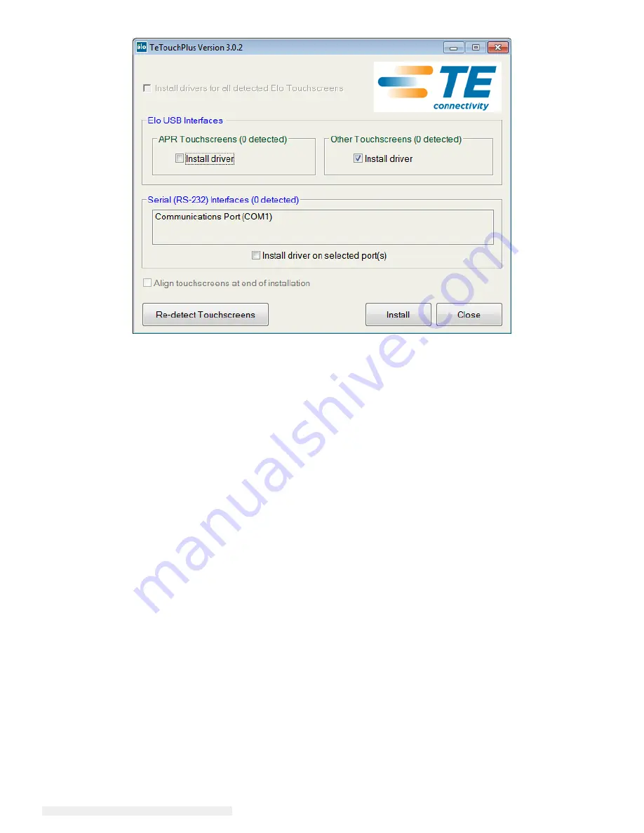
For Windows 7 installations, check the “Install driver” box under “Elo USB Interfaces – Other 
Touchscreens” 


After accepting the end-user license agreement, the drivers will finish installing. 

Reboot your computer after the install is complete. 

Summary of Contents for 2401LM Touchmonitor

Page 1: ...USER MANUAL Elo Touch Solutions 2401LM Touchmonitor SW200127 Rev A ...

Page 2: ...cument is subject to change without notice Elo Touch Solutions Inc and its Affiliates collectively Elo makes no representations or warranties with respect to the contents herein and specifically disclaims any implied warranties of merchantability or fitness for a particular purpose Elo reserves the right to revise this publication and to make changes from time to time in the content hereof without...

Page 3: ...device standards may be susceptible to interference from this device Subjecting the device to conditions beyond the rated performance capabilities may result in emissions in excess of the standard If it is determined that this device produces electromagnetic or other interference it must be disconnected from power until the cause of the problem has been determined and resolved If it is determined ...

Page 4: ...he patient and the Touchmonitor output connecter at the same time Note This symbol alerts the user to important information concerning the operation and maintenance of this unit which should be read carefully to avoid problems This symbol means DC Current This symbol means ON OFF stand by switch Medical and Healthcare Application Disclaimer It is the sole responsibility of any person intending to ...

Page 5: ...ssified as ORDINARY EQUIPMENT not intended or evaluated for use in the presence of flammable anesthetic mixture with air oxygen or nitrous oxide Mode of Operation CONTINUOUS OPERATION Environmental conditions for transport and storage Temp Operating 0 C to 40 C Storage Transportation 20 C to 65 C Humidity non condensing Operating 20 to 80 Storage Transportation 10 to 90 Altitude Operating 0 to 3 0...

Page 6: ...ods are referred to the following standards Emission Immunity CISPR11 2009 A1 2010 ED 5 1 Grp I Class B IEC61000 4 2 2008 ED 2 0 AS NZS CISPR 11 2011 Grp 1 Class B IEC61000 4 3 2006 A1 2007 A2 2010ED 3 2 IEC 61000 4 4 2012 ED 3 0 EN 61000 3 2 2006 A1 2008 A2 2009 Class D IEC 61000 4 5 2005 ED 2 0 IEC 61000 3 3 2008 IEC 610004 6 2008 ED 3 0 IEC 61000 4 8 2009 ED 2 0 IEC 61000 4 11 2004 ED 2 0 ...

Page 7: ...such an environment Emissions test Compliance Electromagnetic environment guidelines RF emissions CISPR 11 Group 1 The 2401LM Touchmonitor for Healthcare Applications uses RF energy only for its internal function Therefore its RF emissions are very low and are not likely to cause any interference in nearby electronic equipment RF emissions CISPR 11 Class A The 2401LM Touchmonitor for Healthcare Ap...

Page 8: ...of a typical commercial or hospital environment Surge IEC 61000 4 5 1 kV line s to line s 2 kV line s to earth 1 kV line s to line s 2 kV line s to earth Mains power quality should be that of a typical commercial or hospital environment Voltage Dips Short Interruption and Voltage Variations on Power Supply Input Lines IEC 61000 4 11 5 UT 95 dip in UT for 0 5 cycle 40 UT 60 dip in UT for 5 cycles 7...

Page 9: ... manufacturer and d is the recommended separation distance in metres m Field strengths from fixed RF transmitters as determined by an electromagnetic site survey1 should be less than the compliance level in each frequency range2 Interference may occur in the vicinity of equipment marked with the following symbol NOTE 1 At 80 MHz and 800 MHz the higher frequency range applies NOTE 2 These guideline...

Page 10: ...hcare Applications as recommended below according to the maximum output power of the communications equipment Rated Maximum Output Power of Transmitter W Separation Distance According to Frequency of Transmitter m 150 kHz to 80 MHz 80MHz to 800 MHz 800 MHz to 2 5 GHz 0 01 0 12 0 12 0 23 0 1 0 37 0 37 0 74 1 1 2 1 2 2 3 10 3 7 3 7 7 4 100 12 12 23 For transmitters rated at a maximum output power no...

Page 11: ...7 Rev A Page 11 of 32 Table of Contents Chapter 1 Introduction 12 Chapter 2 Installation 13 Chapter 3 Mounting 17 Chapter 4 Operation 19 Chapter 5 Technical Support 23 Chapter 6 Safety Maintenance 24 Chapter 7 Regulatory Information 26 Chapter 8 Warranty Information 30 Index 31 ...

Page 12: ...LED backlight significantly reduces power consumption and eliminates mercury compared to CCFL backlit panels Other features that enhance this LCD monitor s performance are Plug Play compatibility built in speakers and headphone output capability on screen display OSD controls and a family of peripherals including webcam and magnetic stripe reader Precautions Follow all warnings precautions and mai...

Page 13: ...pen the carton and verify the following items are present Touchmonitor with protective sheet for its face Elo TouchTools CD Quick Install Guide DVI cable VGA cable USB cable AC DC power adapter AC Power Cable Audio Cable Serial Cable Connector Panel Interfaces Remove the cable cover on the back of the unit to access the Touchmonitor s connector panel ...

Page 14: ...d your PC s USB port 3 Connect the audio cable between the monitor s Audio In jack and your audio source 4 Select the correct power cable for your region Connect the cable between the AC power source and the power adapter s input connector Connect the power adapter s DC output connector to the monitor s input power jack 5 Be sure to reinstall the cable cover and secure with appropriate screws Cabl...

Page 15: ...site www elotouch com for The most up to date touch driver versions Additional touch driver information Detailed touch driver installation guides Touch drivers for other operating systems Download the appropriate driver for your application and follow the onscreen prompts For Windows XP Vista Server 2003 Server 2008 and WEPOS installations install the USB Touchscreen Drivers when prompted If you d...

Page 16: ...1LM SW200127 Rev A Page 16 of 32 For Windows 7 installations check the Install driver box under Elo USB Interfaces Other Touchscreens After accepting the end user license agreement the drivers will finish installing Reboot your computer after the install is complete ...

Page 17: ...ounting orientation The holes located on the top and bottom of the Touchmonitor case are for ventilation Do not block cover or insert anything inside the ventilation slots Rear VESA Mount A four hole 100x100mm mounting pattern for M4 screws is provided on the rear of the monitor Remove the stand using a Phillips screwdriver to access this mounting interface The VESA FDMI compliant mounting is code...

Page 18: ...of the stand base for mounting or securing VESA Mounting Options The following companies provide VESA mounting devices compatible with your touch monitor GCX 800 228 2555 707 773 1100 www gcx com Ergotron 800 888 8458 651 681 7600 www ergotron com Innovative Office Products 800 524 2744 610 253 9554 www innov office prod com MRI 800 688 2414 www mediarecovery com ...

Page 19: ...disuse are planned Touch Your IntelliTouch Touchmonitor is factory calibrated and should not need manual calibration unless the input video is not fully scaled to the native resolution or the touch experience needs to be calibrated to a specific user Video A display s native resolution is its width and height measured in number of pixels Generally for best performance an image displayed on this mo...

Page 20: ...splayed Function when OSD is displayed Menu Display OSD main menu Return to previous OSD menu Display OSD Contrast submenu Increase value of selected parameter select next menu item Display OSD Brightness submenu Decrease value of selected parameter select previous menu item Select Enter Auto Adjust feature VGA mode only Select submenu to enter Using the OSD buttons controls an on screen graphical...

Page 21: ...centered OSD V position Moves the OSD vertically on the display Default centered OSD Timeout Adjusts how long a period of OSD button inactivity the Touchmonitor will wait before closing the OSD The adjustable range is between 45 and 255 seconds Default 45 seconds Auto Adjust Automatically adjusts the system clock to the input analog VGA video signal affecting the H position V position Clock and Ph...

Page 22: ...he Menu Up Down or Select keys will have no effect on the system Press and hold the Menu and Down buttons for two seconds to enable disable the Power Locking feature When the Power Locking is enabled pressing the power switch will have no effect on the system Audio When headphonesare plugged into the headphone output jack the internal speakers turn off and audio is played over the headphones Volum...

Page 23: ...t Monitor display is blank If the Power Status LED is blinking the monitor or Computer Module may be in SLEEP mode Press any key move the mouse touch the Touchscreen to see if the image reappears Monitor displays an Out Of Range message Adjust your computer s resolution timing mode to be within the allowable timing ranges specified for your Touchmonitor see website for specifications Touch functio...

Page 24: ... an unauthorized power cord might invalidate your warranty Ensure that your installation is equipped to maintain the specified environmental conditions listed in the Technical Specifications chapter Care and Handling The following tips will help keep your Touchmonitor functioning at an optimal level Disconnect the AC power cable before cleaning To clean the display unit cabinet use a clean cloth l...

Page 25: ...reserved User Manual 2401LM SW200127 Rev A Page 25 of 32 Waste Electrical Electronic Equipment Directive WEEE This product should not be disposed of with household waste It should be deposited at a facility that enables recovery and recycling ...

Page 26: ...l safety or CE Mark Certification for emissions or immunity as required by the following standards This Information Technology Equipment ITE is required to have a CE Mark on the Manufacturer s label which means that the equipment has been tested to the following Directives and Standards This equipment has been tested to the requirements for the CE Mark as required by EMC Directive 89 336 EEC as in...

Page 27: ...sion levels and may also present a lethal shock hazard to the user If you need additional help consult your dealer manufacturer or an experienced radio or television technician III Agency Certifications The following certifications and marks have been issued or declared for this monitor CE marking to low voltage directive and EMC directive US NRTL mark e g UL Canadian NTRL mark e g CSA and ICES EM...

Page 28: ...irement in SJ T11363 2006 X Indicates that this toxic or hazardous substance contained in at least one of the homogeneous materials used for this component is above the limit requirement in SJ T11363 2006 For items marked with X exemptions were taken according to EU RoHS Explanation of Markings 1 In accordance with the SJ T11364 2006 requirement the electronic information products are marked with ...

Page 29: ...put 100 240VAC 50 60Hz Output 12VDC minimum 3A LPS VI Monitor Specifications Electrical Ratings Input 12VDC 3A Operating Conditions Temperature 0 C 35 C Humidity 20 to 80 non condensing Altitude 0 to 3 048m Storage Conditions Temperature 20 C 50 C Humidity 10 to 90 non condensing Altitude 0 to 12 192m ...

Page 30: ...y Seller to be defective Modification or repair of Products may at Seller s option take place either at Seller s facilities or at Buyer s premises If Seller is unable to modify repair or replace a Product to conform to the warranty set forth above then Seller shall at Seller s option either refund to Buyer or credit to Buyer s account the purchase price of the Product less depreciation calculated ...

Page 31: ...d Immunity Information 26 Environmental conditions 5 European Standards and Classifications 6 Explanation of Markings 28 grounding power cord 24 headphones 22 INGRESS PROTECTION 5 Installing Software Drivers 15 internal speakers 22 Lockouts 22 OSD and Power 22 Mode of Operation 5 Monitor Specifications 29 Mounting Information 17 native resolution 19 online self help 23 On Screen Display 20 Operati...

Page 32: ... the extensive range of Elo touch solutions visit our website at www elotouch com or simply call the office nearest you North America Elo Touch Solutions 1033 McCarthy Blvd Milpitas CA 95035 Tel 800 ELO TOUCH Tel 1 408 597 8000 Fax 1 408 597 8050 customerservice elotouch com Europe Tel 32 0 16 70 45 00 Fax 32 0 16 70 45 49 elosales elotouch com Asia Pacific Tel 86 21 3329 1385 Fax 86 21 3329 1400 ...

Reviews: