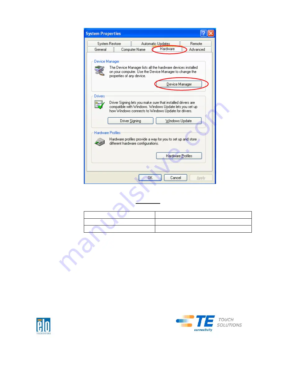
background image


2.


Double


click


the


“Ports


(COM


&


LPT)”


and


check


all


of


these


“USB


Serial


Port”


settings


must


be


IDENTICAL


as


the


following


table.


Description


Location


USB


Serial


Port


(COM3)


On


USB


Serial


Converter


A


USB


Serial


Port


(COM4)


On


USB


Serial


Converter


B


3.


If


you


see


a


situation


as


below,


it


shows


the


operating


system


has


reassigned


these


serial


ports.


You


need


to


correct


it


manually.


C-Series Touchcomputer for Healthcare Applications User Guide


31


Summary of Contents for 19CX

Page 1: ...C Series Touchcomputer for Healthcare Applications User Guide C Series LCD Multi function Touchcomputer 19 model shown...

Page 2: ...Series Touchcomputer for Healthcare Applications User Guide Multi function Touchcomputer Revision A SW601689 1 800 ELOTOUCH 1 800 356 8682 www elotouch com C Series Touchcomputer for Healthcare Applic...

Page 3: ...ouch Solutions business unit in the TE Connectivity Ltd family of companies collectively TE makes no representations or warranties with respect to the contents herein and specifically disclaims any im...

Page 4: ...erformance capabilities may result in emissions in excess of the standard If it is determined that this device produces electromagnetic or other interference it must be disconnected from power until t...

Page 5: ...f accessory equipment should include Use of accessory in the patient environment Evidence that the safety certification of the accessory has been performed in accordance to the appropriate IEC 60601 1...

Page 6: ...European Union Medical Device Directive United States Federal Food Drug and Cosmetic Act regulations of the United States Food and Drug Administration FDA and for obtaining and maintaining any requir...

Page 7: ...air oxygen or nitrous oxide Mode of Operation CONTINUOUS OPERATION Environmental conditions for transport and storage Temp Operating 0 o C to 35 o C Storage Transportation 30 o C to 60 o C Humidity no...

Page 8: ...andards Emission Immunity CISPR11 2003 A1 2004 IEC61000 4 2 2008 ED 2 0 A2 2006 Group I Class A IEC61000 4 3 2006 A1 2007ED 3 0 CISPR 22 2005 A1 2005 Class A IEC 61000 4 4 2004 A1 2010 ED 2 0 AS NZS C...

Page 9: ...issions test Compliance Electromagnetic environment guidelines RF emissions CISPR 11 Group 1 The 19CX 22CX Touchcomputer for Healthcare Applications uses RF energy only for its internal function There...

Page 10: ...ical commerical or hospital environment Surge IEC 61000 4 5 1 kV line s to line s 2 kV line s to earth 1 kV line s to line s 2 kV line s to earth Mains power quality should be that of a typical commer...

Page 11: ...should assure that it is used in such an environment including cables than the recommended separation distance calculated from the equation applicable to the frequency of the transmitter Recommended...

Page 12: ...onment due to fixed RF transmitters an electromagnetic site survey should be considered If the measured field strength in the location in which the 19CX 22CX Touchcomputer for Healthcare Applications...

Page 13: ...r of the communications equipment Separation Distance According to Frequency of Transmitter Rated Maximum Output Power of Transmitter W 150 kHz to 80 MHz 80MHz to 800 MHz 800 MHz to 2 5 GHz 0 0 1 0 1...

Page 14: ...ut Panel 14 Chapter 3 Options and Upgrades 15 Adding Optional Peripherals 15 Magnetic Stripe Reader MSR 16 Customer Display 18 Fingerprint Reader FPR 19 Cash Drawer Port Card 20 Second VGA Port Card 2...

Page 15: ...C Series Touchcomputer for Healthcare Applications xv Regulatory Information 38 Warranty 41 Index 43...

Page 16: ...d test your touchcomputer For information on peripheral options refer to Chapter 3 Options and Upgrades Unpacking Your Touchcomputer Check that the following items are present and in good condition C...

Page 17: ...an operating system the initial setup of the operating system takes approximately 5 10 minutes Additional time may be needed depending on touchcomputer hardware configurations and connected devices To...

Page 18: ...ish is set as the default language but you can change this language to suit your preferences 1 After the TE logo shows up press F8 frequently to enter Advanced Boot Options 2 Select Repair your comput...

Page 19: ...uage 7 Click Inject Selected Language 8 The following window shall be presented 9 After the language package is installed correctly press any key to exit this window 10 Click Exit Exit Restart C Serie...

Page 20: ...ime and currency and keyboard layout of the touchcomputer After making any changes click Next to continue Choosing the Computer Name For Windows 7 OS OS Only When the following window appears you can...

Page 21: ...S OS Only When the following window appears you can select one of the update options of the touchcomputer In general you can choose Use recommended settings as your default option After making any cha...

Page 22: ...letes the installation of the touchcomputer Calibrating the Touchscreen The touchscreen is pre calibrated for accurate touch response If for any reason the touchscreen needs to be recalibrated right c...

Page 23: ...ck the Align button This launches the calibration program The window shown below opens Follow the instructions to calibrate the touchscreen C Series Touchcomputer for Healthcare Applications User Guid...

Page 24: ...designed to work with ISO metric M4 screws Mounting screws are not included with the product but should be readily available at any hardware store Refer to the figure below for the location of the ho...

Page 25: ...T E R 2 OPERATION This chapter describes how to control the On Screen Display OSD power buttons and I O panel All adjustments made to the OSD and power controls are automatically saved User settings...

Page 26: ...you want to change is shown press the SELECT button 3 To adjust the value of the function 4 Pressing the RIGHT button increases the value of the selected OSD control option 5 Pressing the LEFT button...

Page 27: ...OSD Adjusts H position V position and OSD timeout H position Adjusts the OSD menu screen position left or right V position Adjusts the OSD menu screen position up or down Timeout Adjusts the amount o...

Page 28: ...LE or PWR DISABLE 9 When the power button lock feature is activated the power button is disabled L E D Functionality The C Series base has a LED indicating the state of the touchcomputer The table bel...

Page 29: ...used to secure the cable cover to the touchcomputer Below are the I O descriptions by model C3 models C2 models Note The DB9 Serial COM ports are defaulted from left to right COM3 and COM4 Note As a s...

Page 30: ...urchase separately as field installable kits Magnetic stripe reader MSR Customer display Fingerprint reader FPR Wireless adapter Cash Drawer Port Expansion Card Second VGA port expansion card Second h...

Page 31: ...ication and drivers can be found in the following directory or on www elotouch com C EloTouchSystems SetupFiles Peripherals The MSR is a USB 2 0 device that reads all three data stripes on standard cr...

Page 32: ...Accessories Notepad 11 Slide the card through the MSR and verify that the data is displayed in the application window Testing in USB MSR Human Interface Device HID Mode 12 Double click the MagSwipe HI...

Page 33: ...bottom left and right of the touchcomputer Software application and drivers can be found on www elotouch com Feature Description Display type Vacuum fluorescent display Display color Green Display pat...

Page 34: ...al technology gives the highest quality fingerprint scans and reliability Fingerprint reader specifications are shown in the table below Feature Specification Fingerprint reader DigitalPersona U are U...

Page 35: ...le expansion slot This card provides 2 x 12V Powered USB ports 1 x 12V or 24V selectable cash drawer RJ11 port The voltage setting can be set via jumper on the card prior to installing into the touchc...

Page 36: ...ter can be installed as an option in the C Series touchcomputer in the I O area under the cable cover Typical specifications for the wireless card are USB module Compliant to USB 2 0 industry standard...

Page 37: ...solid state drive can be added to or used to replace the original hard disk drive This addition provides additional performance and is more mechanically reliability in harsh environments Part number E...

Page 38: ...in conjunction with a second HDD kit to provide RAID 0 and 1 functionality Software drivers can be found in the following directory or on www elotouch com C EloTouchSystems SetupFiles Peripherals Par...

Page 39: ...00x1200 1280x1024 640x480 352x388 320x240 176x144 160x120 Auto Frame Rate 5fps max 2 0 megapixels 1600x1200 24fps max VGA mode 640x480 Field Of View FOV 66 Focus Range 40cm Infinity Supported Operatin...

Page 40: ...lug into an outlet that has not been configured for this purpose Do not use a damaged power cord Only use the power cord that comes with your Elo TouchSystems touchcomputer Use of an unauthorized powe...

Page 41: ...dilute aqueous cleaning solutions non ammonia based according to directions is recommended Do not spray cleaning solution directly onto touchscreen always use a cloth or towel that has been lightly p...

Page 42: ...with household waste It should be deposited at an appropriate facility for recovery and recycling Recovering the Operating System If for any reason the touchcomputer s operating system and software n...

Page 43: ...the recovery DVD to recover the touchcomputer Recovery DVD s can be ordered if necessary from TE Touch Solutions customer service 1 Connect the USB DVD drive to the touchcomputer 2 Place the recovery...

Page 44: ...d Prompt window type win7 to start recovery process for Windows 7 OS 6 Follow the on screen instruction to complete recovery NOTE All data is deleted during the recovery process The user must back up...

Page 45: ...E After you recovered your touchcomputer by using the included image the operating system might reassign your USB Serial Ports during the first bootup You can follow the instructions below to reassign...

Page 46: ...table Description Location USB Serial Port COM3 On USB Serial Converter A USB Serial Port COM4 On USB Serial Converter B 3 If you see a situation as below it shows the operating system has reassigned...

Page 47: ...nge to USB Serial Port COM5 USB Serial Port COM3 USB Serial Port COM6 USB Serial Port COM4 Thus the settings for these USB Serial Ports should begin at COM3 and end at COM4 in order 4 To correct it pl...

Page 48: ...t of these USB serial ports so the Location should be on USB Serial Converter A Please assign this serial port to COM3 COM4 for the USB Serial Converter B C Series Touchcomputer for Healthcare Applica...

Page 49: ...Change to COM3 C Series Touchcomputer for Healthcare Applications User Guide 34 Select Port Settings Click Advanced Location Information...

Page 50: ...Manager Follow the same steps to accomplish these settings for other ports After finished right click on Ports COM LPT and click Scan for hardware changes 5 The outcome should be identical as the fol...

Page 51: ...COM3 location USB Serial Converter A COM4 location USB Serial Converter B C Series Touchcomputer for Healthcare Applications User Guide 36...

Page 52: ...chnical assistance on the touchcomputer The web The phone Using the Web For technical support go to www elotouch com go contactsupport For current Elo news product updates and announcements or to regi...

Page 53: ...rd with other than the provided approved type Under no circumstances should an adapter plug be used to connect to a 2 wire outlet as this will defeat the continuity of the grounding wire 2 The equipme...

Page 54: ...Standard EN 55022 Class A and the Low Voltage Directive 2006 95 EC as indicated in European Standard EN 60601 D General Information to all Users This equipment generates uses and can radiate radio fre...

Page 55: ...and remove any I O cables that the digital device does not use Unterminated I O cables are a potential source of high RF emission levels vi Plug the digital device into only a grounded outlet recepta...

Page 56: ...in thirty 30 days after submitting such notice Buyer shall package the allegedly defective Product in its original shipping carton s or a functional equivalent and shall ship to Seller at Buyer s expe...

Page 57: ...CIAL CONSEQUENTIAL INDIRECT OR INCIDENTAL DAMAGES Buyer assumes the risk and agrees to indemnify Seller against and hold Seller harmless from all liability relating to i assessing the suitability for...

Page 58: ...ic stripe reader MSR overview 16 specifications 16 testing 17 maintenance care and handling 25 software 27 mounting options 9 on screen display OSD enabling or disabling menu 12 menu settings 11 opera...

Page 59: ...ing 15 warranty 41 website TE Touch Solutions 37 45 WEEE directive 27 wireless card overview 21 specifications 21 testing 21 www elotouch com Get the latest Product information Specifications News on...

Page 60: ...ution Drive Menlo Park CA 94025 USA 800 ELO TOUCH 800 356 8682 Tel 650 361 4800 Fax 650 361 4747 customerservice elotouch com Europe Tyco Electronics Raychem B V B A TE Touch Solutions Division Diests...

Reviews: