background image


User Manual: 1002L, 1502L 

UM600012 Rev A, Page 21 of 25 


as required by EMC Directive 2004/108/EC as indicated in European Standard EN 55022 Class 
B and the Low Voltage Directive 2006/95/EC as indicated in European Standard EN 60950. 

General Information to all Users: This equipment generates, uses and can radiate radio 
frequency energy. If not installed and used according to this manual the equipment may cause 
interference with radio and television communications. There is, however, no guarantee that 
interference will not occur in any particular installation due to site-specific factors. 

1) In order to meet emission and immunity requirements, the user must observe the following: 

a) Use only the provided I/O cables to connect this digital device with any computer. 

b) To ensure compliance, use only the provided manufacturer’s approved line cord. 

c) The user is cautioned that changes or modifications to the equipment not expressly 
approved by the party responsible for compliance could void the user’s authority to operate 
the equipment. 

2) If this equipment appears to cause interference with radio or television reception, or any 
other device: 

a) Verify as an emission source by turning the equipment off and on. 

If you determine that this equipment is causing the interference, try to correct the interference 
by using one or more of the following measures: 

i) Move the digital device away from the affected receiver.   

ii) Reposition (turn) the digital device with respect to the affected receiver. 

iii) Reorient the affected receiver’s antenna. 

iv) Plug the digital device into a different AC outlet so the digital device and the receiver 
are on different branch circuits. 

v) Disconnect and remove any I/O cables that the digital device does not 
use.(Unterminated I/O cables are a potential source of high RF emission levels.) 

vi) Plug the digital device into only a grounded outlet receptacle. Do not use AC adapter 
plugs. (Removing or cutting the line cord ground may in crease RF emission levels and 
may also present a lethal shock hazard to the user.) 

If you need additional help, consult your dealer, manufacturer, or an experienced radio or 
television technician. 

Summary of Contents for 1002L

Page 1: ...USER MANUAL Elo Touch Solutions 1002L and 1502L Touchmonitors UM600012 Rev A...

Page 2: ...nformation in this document is subject to change without notice Elo Touch Solutions Inc and its Affiliates collectively Elo makes no representations or warranties with respect to the contents herein a...

Page 3: ...25 Table of Contents Chapter 1 Introduction 4 Chapter 2 Installation 5 Chapter 3 Mounting 9 Chapter 4 Operation 11 Chapter 5 Technical Support 16 Chapter 6 Safety Maintenance 18 Chapter 7 Regulatory...

Page 4: ...nd eliminates mercury compared to CCFL backlit panels Other features that enhance this LCD monitor s performance are Plug Play compatibility on screen display OSD controls and a family of optional per...

Page 5: ...t the following items are present Touchmonitor with Stand Stand is not included with 1002L monitor User Manuals CD Japanese language regulatory information pamphlet Quick Install Guide Mini VGA to VGA...

Page 6: ...ouchmonitor ships in the low profile hostess position 1002L monitor does not ship with a stand Low profile hostess position To convert the stand into the high profile upright position secure the thumb...

Page 7: ...performance 2 Connect the USB touch cable between the monitor s USB connector and your PC s USB port 3 Connect the audio cable between the monitor s Audio In jack and your audio source 4 Select the co...

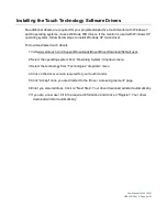
Page 8: ...test touch drivers 1 Visit www elotouch com Support Downloads Driver DriverDownload Default aspx 2 Select the operating system from Operating System dropdown menu 3 Select the technology from Technolo...

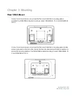
Page 9: ...le The VESA FDMI compliant counting is coded VESA MIS B 75 C and VESA MIS B 100 C For the 15 inch touchmonitor a four hole 75x75mm and 100x100mm mounting pattern for M4 screws is provided on the rear...

Page 10: ...Manual 1002L 1502L UM600012 Rev A Page 10 of 25 Base Mount For the 15 inch touchmonitor a threaded three hole mounting pattern for M4 screws is provided on the bottom of stand base for mounting or sec...

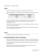
Page 11: ...d host PC out of SLEEP mode similar to moving the mouse or pressing a keyboard key To improve reliability and reduce wasteful power consumption disconnect the power adapter when long periods of disuse...

Page 12: ...r compressing the input image as needed in the X and Y dimensions to fit the display s native resolution An unavoidable byproduct of the scaling algorithms is a loss of fidelity when the computer s ou...

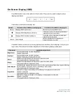
Page 13: ...eo This allows for intuitive adjustment of the following display parameters Parameter Available Adjustment Brightness Increase decrease monitor brightness Default Maximum Contrast Increase decrease mo...

Page 14: ...gains on a scale from 0 to 100 Default User Defined with R G and B all set to 100 OSD Timeout Adjusts how long a period of OSD button inactivity the touchmonitor will wait before closing the OSD The...

Page 15: ...disable the OSD Locking feature When the OSD Locking is enabled pressing any of the Menu Up Down or Select keys will have no effect on the system Press and hold the Menu and Down buttons for two secon...

Page 16: ...e in SLEEP mode Press any key move the mouse touch the Touchscreen to see if the image reappears Check that the signal source device is turned on Check that that there are no loose cable connections M...

Page 17: ...isit www elotouch com products for technical specifications for this device Visit www elotouch com go websupport for online self help Visit www elotouch com go contactsupport for technical support See...

Page 18: ...an optimal level Disconnect the AC power cable before cleaning To clean the display unit cabinet use a clean cloth lightly dampened with a mild detergent It is important that your unit remains dry Do...

Page 19: ...502L UM600012 Rev A Page 19 of 25 Waste Electrical Electronic Equipment Directive WEEE This product should not be disposed of with household waste It should be deposited at a facility that enables rec...

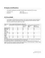
Page 20: ...the limits for a Class B digital device pursuant to Part 15 of FCC Rules These limits are designed to provide reasonable protection against harmful interference in a residential installation This equi...

Page 21: ...ance could void the user s authority to operate the equipment 2 If this equipment appears to cause interference with radio or television reception or any other device a Verify as an emission source by...

Page 22: ...ents Lead Pb Mercury Hg Cadmium Cd Hexavalent Chromium Cr6 Polybrominated Biphenyls PBB Polybrominated Diphenyl Ethers PBDE Plastic Parts O O O O O O Metal Parts X O O O O O Wire and Cable Assembly X...

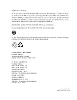
Page 23: ...dily injury or damage to any assets Operating Temperature 0 40 Humidity 20 80 non condensing Storage Temperature 20 60 Humidity 10 90 non condensing 2 It is encouraged and recommended that this produc...

Page 24: ...ive Modification or repair of Products may at Seller s option take place either at Seller s facilities or at Buyer s premises If Seller is unable to modify repair or replace a Product to conform to th...

Page 25: ...utions visit our website at www elotouch com or simply call the office nearest you North America Elo Touch Solutions 1033 McCarthy Blvd Milpitas CA 95035 Tel 800 ELO TOUCH Tel 1 408 597 8000 Fax 1 408...

Reviews: