Elmo 95VDC Installation Manual Download Page 13

Duo User Guide


3-1


Chapter 3:  Installation 

3.1


Site Requirements 

You can guarantee the safe operation of the Duo by ensuring that it is installed in an 
appropriate environment. 

Feature Value 

Ambient operating temperature 

0

°

 to 40

°

C (32

°

 to 104

°

F)  

Maximum operating altitude 

10,000m (30,000ft) 

Maximum relative humidity 

90% non-condensing 

Operating area atmosphere 

No flammable gases or vapors permitted in area 

Models for extended environmental conditions are available. 


The Whistle on the Duo dissipates its heat by convection. The maximum 
operating ambient temperature of 0

°

 to 40

°

C (32

°

 to 104

°

F) must not be 

exceeded. Refer to the Heat Dissipation section of the 

Whistle Installation Guide


for more information. 

3.2


Unpacking the Drive Components 

Before you begin working with the Duo, verify that you have all of its components, as 
follows: 

ƒ


The Duo. 


ƒ


The Composer software and software manual. 

The Duo is shipped in a cardboard box with styrofoam protection.  

To unpack the 

Duo

1.


Carefully remove the Duo from the box and the Styrofoam.  

2.


Check the Duo to ensure that there is no visible damage to the instrument. If any damage 
has occurred, report it immediately to the carrier that delivered your Duo. 

3.


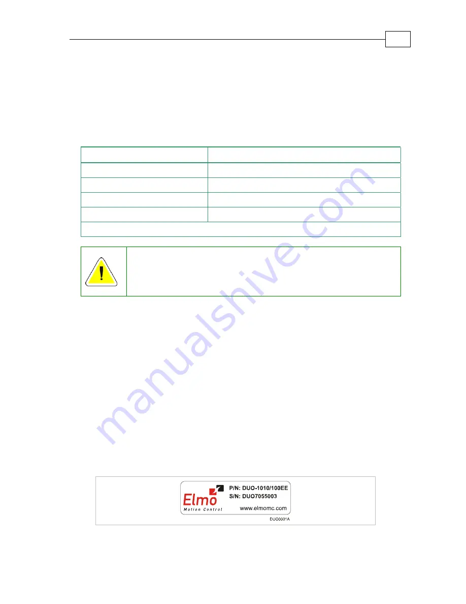
To ensure that the Duo you have unpacked is the appropriate type for your requirements, 
locate the part number sticker on the side of the Duo.                                    It looks like this: 


MAN-DUOUG (Ver. 1.0) 

Summary of Contents for 95VDC

Page 1: ...Duo Integrated Solution Installation Guide June 2007 Ver 1 0...

Page 2: ...mber DUO AXXAXX YYYZZ Axis 1 Version Blank Standard A Advanced Axis 2 Version Blank Standard A Advanced Axis 1 Continuous Current Amps Axis 2 Continuous Current Amps Axis 1 Feedbacks E Incremental Enc...

Page 3: ...ents 3 1 3 3 Mounting the Duo 3 2 3 4 Connecting the Cables 3 3 3 4 1 Wiring the Duo 3 3 3 5 Duo Connectors type 3 5 3 6 Hardware Requirements 3 6 3 7 Duo Block Diagram 3 7 3 8 The Main Power and Moto...

Page 4: ...Interpolated Analog Encoder Sine Cosine A 9 A 6 5 Resolver A 10 A 6 6 Tachometer A 10 A 6 7 Potentiometer A 11 A 6 8 Auxiliary Feedback Port output mode YA 4 4 A 11 A 6 9 Auxiliary Feedback Port inpu...

Page 5: ...munication Cables B 6 B 6 1 RS 232 Option CBL RJ452321 B 6 B 6 2 CAN Open CBL RJ45CAN1 B 7 B 7 Guidelines for Making Your Own Cables B 8 B 7 1 Recommended Wire Cross Sections B 8 Duo Installation Guid...

Page 6: ...o perform tasks such as transporting assembling installing commissioning and operating motors The Duo contains electrostatic sensitive components that can be damaged if handled incorrectly To prevent...

Page 7: ...acts Measuring the electrical contact points with a meter before touching the equipment is recommended 1 2 Cautions The Duo contains hot surfaces and electrically charged components during operation T...

Page 8: ...ts of the relevant requirements of the European Safety of Machinery Directive 98 37 EC as amended and with those of the most recent versions of standards EN60204 1 and EN292 2 at the least According t...

Page 9: ...Nopen based networking operating simultaneously via RS 232 and CANopen DS 301 DSP 305 DSP 402 communications and featuring a third generation programming environment Current velocity and position cont...

Page 10: ...r monitoring the motion of the slave axis relative to a master axis via an auxiliary encoder input Pulse and direction inputs Sample rate four times current loop sample time Fast event capturing input...

Page 11: ...ircuits between the motor power outputs and between each output and power input return Recovery from loss of commutation signals and from communication errors 2 3 How to Use this Guide In order to ins...

Page 12: ...Installation Guide contains information about how to use the Duo and Cable Kit The Composer Software Manual which includes explanations of all the software tools that are part of Elmo s Composer softw...

Page 13: ...04 F must not be exceeded Refer to the Heat Dissipation section of the Whistle Installation Guide for more information 3 2 Unpacking the Drive Components Before you begin working with the Duo verify t...

Page 14: ...dbacks E Incremental Encoder and or Halls R Resolver I Interpolated Analog Encoder T Tachometer and Potentiometer Verify that the Duo type is the one that you ordered and ensure that the voltage meets...

Page 15: ...lthough 26 AWG is recommended Use shielded wires for motor connections as well If the wires are long ensure that the capacitance between the wires is not too high C 30 nF is satisfactory for most appl...

Page 16: ...liary Feedback Table 3 2 Connectors on the Front of the Duo Type Function Connector Location CANopen CANopen IN CANopen CANopen OUT RS232 RS232 1 RS232 2 Table 3 3 Connectors on the Top of the Duo Aux...

Page 17: ...Main Feedback 2 12 pin Molex Header P N 90130 3212 I O 2 14 pin Molex Header P N 90130 3214 2 Auxiliary Feedback 16 pin Molex Header P N 90130 3216 2 8 pin RJ 45 Socket CANopen Comm RS232 Comm 2 8 pi...

Page 18: ...VL Motor Power 2 Phoenix 4 pin Plug P N MSTBT 2 5 4 ST 5 08 PE M1 M2 M3 Plug M3 PE 12 pin Molex Plug P N 90142 0012 Main Feedback Feedback 2 B 3 Pin P N 90119 2121 I O 2 14 pin Molex Plug P N 90142 0...

Page 19: ...Duo User Guide MAN DUOUG Ver 1 0 3 7 3 7 Duo Block Diagram Figure 3 2 Duo Block Diagram...

Page 20: ...he phase connection order is arbitrary because the Composer will establish the proper commutation automatically during setup If several motor drive combinations are designed to operate in an identical...

Page 21: ...se twisted and shielded cables for the DC power supply cable A 3 wire shielded cable should be used The gauge is determined by the actual current consumption of the motor Connect the cable shield to t...

Page 22: ...ground near the Auxiliary Supply source Connect the cable shield to the closest ground near the Auxiliary Supply source Before applying power first verify the polarity of the connection Caution Power...

Page 23: ...Figure 3 6 Shared Supply Connection Diagram Duo User Guide MAN DUOUG Ver 1 0 3 11...

Page 24: ...T Supply return SUPRET Supply return SUPRET Supply return 3 CHA Channel A A Sine A S1 Sine A Tac 1 Tacho Input 1 Pos 20V max 4 CHA Channel A complement A Sine A complement S3 Sine A complement Tac 1 T...

Page 25: ...Figure 3 7 Main Feedback Incremental Encoder With Digital Halls Sensors Connection Diagram Figure 3 8 Main Feedback Incremental Encoder Only Connection Diagram Duo User Guide MAN DUOUG Ver 1 0 3 13...

Page 26: ...Figure 3 9 Main Feedback Interpolated Analog Encoder Connection Diagram Figure 3 10 Main Feedback Resolver Connection Diagram Duo User Guide MAN DUOUG Ver 1 0 3 14...

Page 27: ...MAN DUOUG Ver 1 0 3 15 Figure 3 11 Main Feedback Tachometer Feedback with Digital Hall Sensor Connection Diagram for Brushless Motors Figure 3 12 Main Feedback Tachometer Feedback Connection Diagram f...

Page 28: ...Potentiometer Feedback with Digital Hall Sensor Connection Diagram for Brushless Motors Figure 3 14 Main Feedback Potentiometer Feedback Connection Diagram for Brush Motors and Voice Coils Duo User Gu...

Page 29: ...re two modes of operation for this interface Mode 1 Composer Command YA 4 4 see 3 10 2 When the Auxiliary port of the Whistle is set by the software to act as an emulated encoder output this is practi...

Page 30: ...os Encoder Input B2 output Analog Encoder position data emulated in Differential buffered incremental Encoder format Main Feedback Analog Encoder B1 not available Resolver Input B2 output Resolver pos...

Page 31: ...Resolver or Tachometer or Potentiometer Input B1 Buffered Differential Pulse Direction Commands Input B2 Buffered Differential Pulse Direction Commands Output of B1 Auxiliary Feedback B1 Buffered Diff...

Page 32: ...Encoder only The Auxiliary Feedback on the Duo has a 16 pin Molex Header plug Port Pin Signal Function PWR 1 5V Encoder supply voltage PWR 2 COMRET Common return B1 3 NA When YA 4 4 the B1 port is no...

Page 33: ...Figure 3 15 Emulated Encoder Outputs of the Resolver or Analog Encoder Connection Diagram Duo User Guide MAN DUOUG Ver 1 0 3 21...

Page 34: ...return B1 3 CHA Auxiliary channel A input B1 4 CHA Auxiliary channel A complement input B1 5 CHB Auxiliary channel B input B1 6 CHB Auxiliary channel B complement input B1 7 INDEX Auxiliary Index Inpu...

Page 35: ...Duo User Guide MAN DUOUG Ver 1 0 3 23 Figure 3 6 Differential Auxiliary Input Option Block Diagram...

Page 36: ...Duo User Guide MAN DUOUG Ver 1 0 3 24 Figure 3 16 Differential Auxiliary Input Option on Auxiliary Feedback Connection Diagram...

Page 37: ...WR 2 COMRET Common return B1 3 CHA Auxiliary Pulse input B1 4 CHA Auxiliary Pulse complement input B1 5 CHB Auxiliary Direction input B1 6 CHB Auxiliary Direction complement input B1 7 NA Do not conne...

Page 38: ...Figure 3 17 Pulse and Direction Input Option on Auxiliary Feedback Connection Diagram Duo User Guide MAN DUOUG Ver 1 0 3 26...

Page 39: ...put 1 return 3 OUT2 Programmable Digital output 2 4 OUTRET2 Programmable Digital output 2 return 5 IN1 Programmable Digital input 1 6 IN2 Programmable Digital input 2 7 IN3 Programmable Digital input...

Page 40: ...3 11 1 Digital Input The Default Digital Input level Signal is set to 24v PLC Note 5v is also available TTL Figure 3 18 Digital Input Connection Diagram Duo User Guide MAN DUOUG Ver 1 0 3 28...

Page 41: ...3 11 2 Digital Output Figure 3 19 Digital Output Connection Diagram 3 11 3 Analog Input Figure 3 20 Analog Input with Single ended Source Duo User Guide MAN DUOUG Ver 1 0 3 29...

Page 42: ...ramming and timing issues of a CANopen network For ease of setup and diagnostics of CAN communication RS232 and CANopen can be used simultaneously 3 12 1 RS232 Communication Notes for connecting the R...

Page 43: ...e the drain wire to facilitate connection The CANopen communication port is non isolated The male RJ plug must have a shield cover Ensure that the shield of the cable is connected to the shield of the...

Page 44: ...de MAN DUOUG Ver 1 0 3 32 Figure 3 22 CANopen Network Connection Diagram Caution When installing CANopen communications ensure that each servo drive is allocated a unique ID Otherwise the CANopen netw...

Page 45: ...thin the specified range and that the proper plus minus connections are in order 3 14 Initializing the System After the Duo has been connected and mounted the system must be set up and initialized Thi...

Page 46: ...ation alternatives o Sinusoidal vector control o Trapezoidal o DC brush Feedback alternatives o Incremental encoder digital Halls o Incremental encoder only o Digital Halls o Resolver o Sin Cos o Sin...

Page 47: ...on volatile storage of controller parameters and user programs Setup startup and tuning software o Windows based Composer Automatic analysis of kinematics Status indication o Bi color LED Automatic pr...

Page 48: ...against o Short circuit between motor power outputs o Short circuit between each motor power output and DC bus return o Failure of internal power supply o Heatsink over temperature o Under over voltag...

Page 49: ...Duo Installation Guide MAN DUOIG Ver 1 0 A 4 A 3 Duo Dimensions...

Page 50: ...Voltage 95 of supply VDC at f 22 KHz DC and Trapezoidal Commutation Continuous Current Limit Ic A 1 2 5 5 10 15 1 2 5 5 10 15 Sinusoidal Commutation Continuous RMS Current Limit Ic A 0 7 1 8 3 6 7 10...

Page 51: ...ling Motor types AC brushless sinusoidal DC brushless trapezoidal DC brush Linear brushless motor Current control Fully digital Sinusoidal with vector control Programmable PI control filter based on a...

Page 52: ...Analog Halls Tacho Potentiometer Note With all feedback options 1 T with automatic mode switching is activated gap frequency and derivative Velocity command options Analog Internally calculated by ei...

Page 53: ...l encoder frequency Maximum absolute 5 MHz single 20 MHz quadrature Minimum quadrature input period PIN 112 nsec Minimum quadrature input high low period PHL 56 nsec Minimum quadrature phase period PP...

Page 54: ...also support open collector Halls Maximum frequency fMAX 2 kHz A 6 4 Interpolated Analog Encoder Sine Cosine Feature Details Analog encoder format Sine and Cosine signals Analog input signal level Of...

Page 55: ...Maximum operating differential voltage for TAC1 TAC1 20V Maximum absolute differential input voltage for TAC1 TAC1 25V Maximum operating differential voltage for TAC2 TAC2 50V Maximum absolute differ...

Page 56: ...tput current capability Maximum output current IOH max 2 mA High level output voltage VOH 3 0 V Minimum output current IOL 2 mA Low level output voltage VOL 0 4 V Available as options Emulated encoder...

Page 57: ...V Input current 1 A Encoder Hall supply voltage 5V 5 Maximum encoder supply current 200 mA Available as options Differential Encoder inputs Differential Pulse and Direction inputs Edge separation betw...

Page 58: ...nput until execution is complete If input is set to one of the built in functions Home Inhibit Hard Stop Soft Stop Hard and Soft Stop Forward Limit Reverse Limit or Begin execution is immediate upon d...

Page 59: ...nal resistor RL must be selected to limit output current to no more than 10 mA max Io VOL Vcc RL Executable time If output is set to one of the built in functions Home flag Brake or AOK execution is i...

Page 60: ...Storage temperature 20 to 85 C 4 to 185 F Humidity 90 maximum non condensing Maximum Operating Altitude 10 000m 30 000 feet Protection level IP20 A 10 Compliance Standards Specification Details ISO900...

Page 61: ...ith UL60950 Safety of information technology equipment including electrical business equipment In compliance with EN60204 1 Low voltage directive 73 23 EEC A 10 3 EMC Specification Details In complian...

Page 62: ...Duo Installation Guide B 1 Appendix B Cables Optional B 1 Cable Photos Main Feedback CBL HDRFB 001 Auxiliary Feedback CBL HDRAUX 001 I O CBL HDRIO 001 RS 232 Com CBL RJ452321 CAN Com CBL RJ45CAN1...

Page 63: ...and or individual cables in multiples of 10 each are available from Elmo Cable Application Cable Part No QTY Main Feedback CBL HDRFB 001 2 Auxiliary Feedback CBL HDRAUX 001 2 I O CBL HDRIO 001 2 RS 23...

Page 64: ...the Duo It is open on its other side so that it can be connected to customer specific motor connector Pin No Color Signal Pairs 1 Brown 5V 2 White COMRET pair 3 Cyan CHA 4 Orange CHA pair 5 Purple CHB...

Page 65: ...on the Duo Pin No Color Signal Pairs 1 Brown 5V 2 White COMRET pair 3 Cyan CHA 4 Orange CHA pair 5 Purple CHB 6 Black CHB pair 7 Red INDEX 8 Blue INDEX pair 9 Pink CHAO 10 Grey CHAO pair 11 Yellow CH...

Page 66: ...port on the Duo Pin No Color Signal Pairs 1 Orange OUT1 2 Cyan OUTRET1 pair 3 Black OUT2 4 Purple OUTRET2 pair 5 Brown IN1 6 White IN2 pair 7 Green IN3 8 Yellow IN4 pair 9 Gray IN5 10 Pink IN6 pair 11...

Page 67: ...options RS 232 full duplex CANopen B 6 1 RS 232 Option CBL RJ452321 RJ45 Pin No Color D type Female Pin No Signal Description 1 2 3 Brown 2 Tx RS232 Transmit 4 5 White 5 COMRET Communication Return 6...

Page 68: ...in No Signal Description 1 Green 7 CAN H CAN_H bus line 2 Yellow 2 CAN_L CAN_L bus line 3 White 3 CAN_GND CAN ground 4 5 7 8 1 body Drain Wire body shield cable shield The shields of the RJ 45 and D t...

Page 69: ...ough 24 AWG is recommended Use shielded wires for motor connections as well If the wires are long ensure that the capacitance between the wires is not too high C 30 nF is satisfactory for most applica...

Reviews: