background image


Elma Schmidbauer GmbH  Gottlieb-Daimler-Str. 17  D-78224 Singen  Tel49 (0) 7731 / 882-0  Fax +49 (0) 7731 / 882-266  

[email protected]


www.elma-ultrasonic.com


document ref. 1076604 

Operating Instructions 


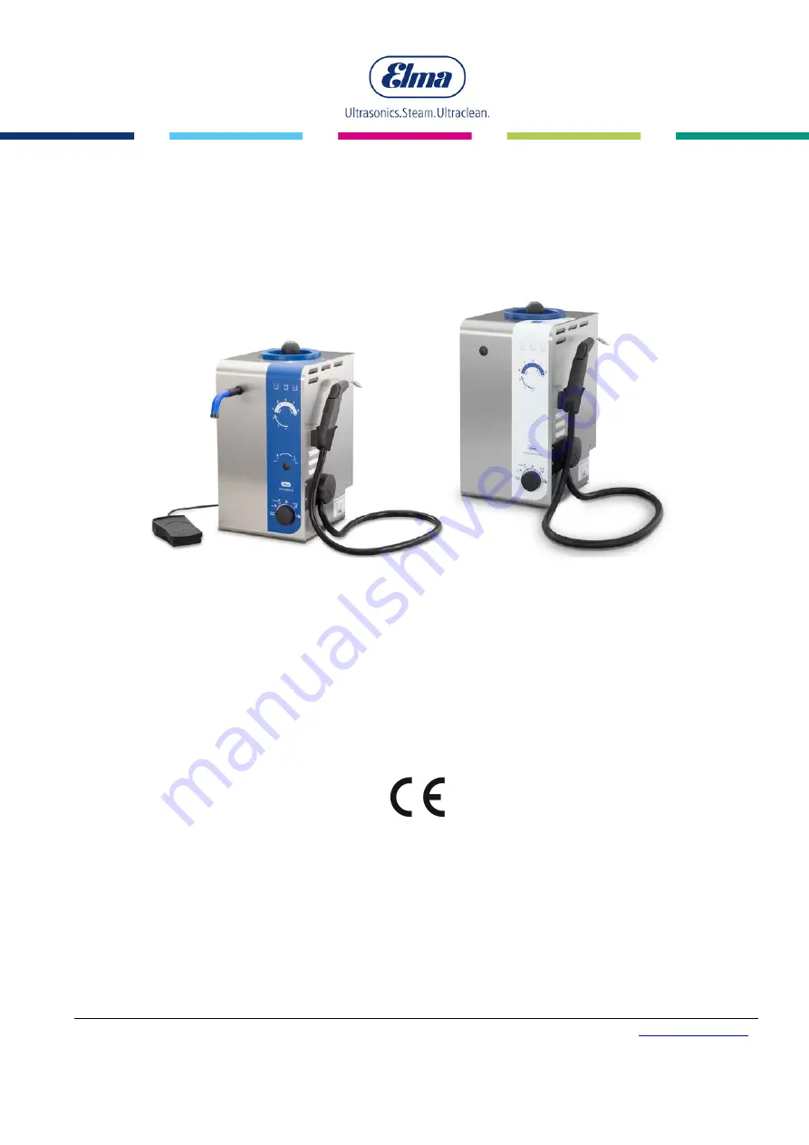
Elmasteam 8 

 basic 

 med


High-performance steam cleaner 


 English 


Summary of Contents for Elmasteam 8

Page 1: ... Daimler Str 17 D 78224 Singen Telephone 49 0 7731 882 0 Fax 49 0 7731 882 266 info elma ultrasonic com www elma ultrasonic com document ref 1076604 Operating Instructions Elmasteam 8 basic med High performance steam cleaner English ...

Page 2: ... Operating Displays 21 3 6 4 Saturated Steam wet dry optional 22 3 6 5 Programme Selection 23 3 6 6 Handpiece optional 24 3 6 7 Luer Lock Connection med 25 3 6 8 Fixed Nozzle optional 26 4 Commissioning 27 4 1 Installation and Connection Conditions 27 4 1 1 Assembling the Mains Supply Cable 28 4 2 Assembling the Fixed Nozzle Option 29 4 2 1 Assembling the Foot Switch option 31 4 3 Assembling the C...

Page 3: ...ecting lock 70 7 4 5 Service Descaling 71 7 4 6 Settings 75 8 Safety Maintenance Repair Works 79 8 1 Regular Visual Controls 79 8 2 Flush the Pressure Vessel 80 8 2 1 Cleaning the Sieve in the Water Connection 83 8 3 Wear and Tear Parts 84 8 3 1 O ring in the Pressure Vessel Screw Cap 84 8 3 2 O ring Nozzle 84 8 3 3 Seal on the Collecting Tray 84 8 3 4 Hose handpiece 84 8 4 Safety Valve 85 8 4 1 I...

Page 4: ...or problems that are not covered in this operating manual which are or not of a sufficient manner 2 Important Safety Instructions INFORMATION Please read these instructions carefully before use and only operate this electrical device in accordance with the hereby entered instructions and information Note additionally the instructions of this operating manual with regard to the country specific saf...

Page 5: ...st general risks of injury and or property damage This symbol warns of a risk of damage to property and indicates additional information Signal words in these instructions The signal word danger warns of serious injury or death The signal word warning warns of serious injury The signal word caution warns of minor to moderate injuries The signal word information warns of material damage and indicat...

Page 6: ...lways wear suitable PPE e g protective gloves protective footwear protective clothing Place the device in the lock position during application breaks The device automatically switches off after expiry of the set time limit INFORMATION Parts in the device can be damaged The connected pressurised air must not exceed a pressure of 6 bar Applies only to devices with optional compressed air inlet INFOR...

Page 7: ... as one segment is illuminated on the value scale on the gauge Only fill with potable water or distilled DI Descaling as an exception INFORMATION Refer to the Operating Instructions Read the operating instructions completely before you commence working with the device Failure to observe these operating instructions can cause serious injury or damage to the device Always retain the operating instru...

Page 8: ...he device when visible damage is identified Always contact the supplier and transport company in such cases Position the device on a stable level dry surface which is insensitive to moisture The ventilation slits must never be covered Ensure that the workplace is sufficiently ventilated The device must only be connected to a properly grounded connection socket to comply with the safety regulations...

Page 9: ...n degree of maximum 5µm Remove excessive carbon dust by installing a micro filter on the upstream side of the valve If excessive carbon dust is generated by the compressor then this may adhere in the valve and cause a malfunction Maximum compressed air temperature 40 C Do not exceed the stated maximum air pressure as this may result in personal injury and increased material wear and tear The user ...

Page 10: ...e prescribed maintenance works have not been conducted WARNING High temperatures on the nozzle with nozzle tube Serious injuries from burns Only touch the said areas with personal protective equipment e g protective gloves Allow the unit to cool down before touching any part thereof WARNING Hot vapours hot liquids Risk of scalding from open pressure vessel screw cap Hot water splashes and evaporat...

Page 11: ...locity causes electrostatic charge generated by friction to accumulate on the nozzle as well as on the product to be cleaned The electrostatic charge developed on the handpiece is continuously dissipated via the ground connection of the device Depending on external conditions such as insufficient conductivity of the floor and or shoes dissipation of electrostatic charge of the product to be cleane...

Page 12: ...isk of detachment when pre cleaning of instruments made of composite material e g steel plastic in bipolar forceps Steam cleaner for manual pre cleaning or treatment of instruments Only medical devices that are approved and reusable for reprocessing must be cleaned refer to the information from the medical device manufacturer in accordance with EN ISO 17664 The operation must only be performed by ...

Page 13: ...ation of Aerosols Transmission of pathogens For protection of the personnel in the area of instrument cleaning a suitable suction device and drip device are strongly recommended e g Elma steam workplace with autonomous suction and Hepa Filter Wear a suitable mouth protection Generation of Aerosols ...

Page 14: ...ushing Set 3 O rings for pressure vessel screw cap 1 Water Hose fixed water supply 1 Luer Lock connection set med 1 Fixed Nozzle optional 1 Set of Operating Instructions 1 Information Data Sheet for Water Quality 1 Information Data Sheet for the Warranty Conditions Accessories 1 canister with hose ventilation and level monitoring 8 piece adapter set for Luer Lock connection med Fixed nozzle with 2...

Page 15: ...ir MED Design with Luer Lock P Pump ND Saturated Steam ES8 HS O ES8MED HS O O ES8 HS FD O O ES8 HS FD DL O O O ES8 HS DL O O ES8MED HS DL O O O ES8 FD O ES8 FD DL O O ES8 P HS O O ES8 P HS FD O O O ES8 P HS FD DL O O O O ES8 P HS DL O O O ES8 P HS DL ND O O O O ES8MED P HS DL O O O O ES8 P FD O O ES8 P FD DL O O O Table 3 1 2 Device Overview ...

Page 16: ...ufacturer 3 3 Operational Method Water is heated by a heater to 185 C in a manually or automatically filled pressure vessel A steam pressure of maximum 8 bar is thereby generated The steam is provided through the nozzle s for availability Steam and hot water are thereby mixed from the pressure vessel Optional The mixing ratio can be adjusted via the rotary knob for wet dry Operate the device exclu...

Page 17: ...vel at 8 bar dBA 93 Pressure in the pressure vessel bar 8 Pressure vessel volumes litres 5 Maximum filling volume litres 3 8 Heating up time minutes 20 Steam temperature outlet Approximately 160 C Steam temperature in the boiler Approximately 185 C Dimensions without manual unit bracket and fixed nozzle W x D x H mm 285 x 350 x 520 Material housing Stainless steel Pressure vessel Stainless steel a...

Page 18: ...5 Safety Equipment and Devices The devices are equipped with all prescribed safety devices and or equipment such as e g Safety pressure relief valve Safety pressure vessel closure for inadmissible opening of the pressure vessel screw on the filler pipe Low voltage in handpiece ...

Page 19: ...tor 1 8 Rotary knob wet dry Setting the mixing ratio Refer to Chapter 6 3 for a description Rotary knob for programme selection Turn the rotary knob to select the function and press the rotary knob to confirm the selection Refer to Chapter 6 4 for a description Bracket For handpiece optional Handpiece optional Ventilation Openings lateral on the housing Drip Tray Manual filling for overflowing wat...

Page 20: ...n for Water Supply to the Pump optional Connection for Exhaust Hose for the Canister optional Ball Valve with Protective Cover for emptying the pressure vessel and for maintenance works Connection for Filling Level Sensor on the Canister optional Connection for Foot Switch for the assembled Fixed Nozzle optional Connection for Mains Supply Cable On Off Switch Mains switch illuminates as green in o...

Page 21: ...rating pressure flashes green until the pressure is achieved Step Display D for programme controlled descaling programme Figure 3 6 3 Operating Displays Illuminates or flashes red for warnings for Filling Level Descaling Illuminates or flashes blue to indicate the filling level status in the pressure vessel or the optional canister Illuminates or flashes orange to signal descaling for the device I...

Page 22: ... with the handpiece Figure 3 6 4 Rotary knob wet dry Turn the rotary knob A to the end limit wet 100 operating with saturated steam Turn the rotary knob A to the end limit dry 100 operating with dry steam The intensity of the mixing ratio of the steam function will be regulated by turning the rotary knob A as 0 100 The mixing ratio can also be adjusted during the steam operation Wet Dry A ...

Page 23: ...lock Figure 3 6 5 D Figure 3 6 5 Rotary knob programme selection steam outlet to drain the residual pressure in the pressure vessel before opening the pressure vessel screw cap Steam can be discharged through the handpiece or fixed nozzle Chapter 6 4 1 soft for the pressure range 4 6 bar The adjusted operating pressure on the gauge illuminates as green until the pressure has been built up reduced ...

Page 24: ...rolled descaling Follow the step indicator on the gauge Chapter 6 4 5 Service Descaling Settings for steam soft steam strong time to lock time to eco measurement value lime content reset the device to factory settings Chapter 6 4 6 Settings 3 6 6 Handpiece optional Figure 3 6 6 Handpiece Activated Compressed Air optional Activated Steam Activated Steam both button pressed Nozzle Pipe Nozzle Pipe o...

Page 25: ...ATION The Luer Lock connection on the device is intended for connecting special adapters that are designed for cleaning the inside of hollow instruments The medical adapter is included in the scope of delivery for medical devices Figure 3 6 7 Handpiece with Luer Lock Connection med Luer Lock Connection med A A ...

Page 26: ...on 26 BA_Elmasteam_8_Vers 07 2016 Elma Schmidbauer GmbH 3 6 8 Fixed Nozzle optional INFORMATION The steam operation with the fixed nozzle will be activated via the foot switch Figure 3 6 8 Fixed Nozzle Fixed Nozzle A A ...

Page 27: ...orkplace The device may only be operated in well ventilated internal areas at an ambient temperature of 5 40 º C 41 104 F at a maximum relative humidity of 80 at 31 C 87 8 F decreasing linearly to 50 relative humidity at 40 C 104 F With a mains power supply when the voltage fluctuations do not exceed 10 of the nominal value Between 5 30 C 41 86 F the device is ready for operation at a relative hum...

Page 28: ...vice 4 1 1 Assembling the Mains Supply Cable INFORMATION Assembling the Mains Supply Plug Observe the technical data on the nameplate Figure 4 1 1 C Make sure that the electrical plug socket has the same voltage as that indicated on the nameplate The plug socket for the mains supply cable must be easily accessible In an emergency pull the mains plug out of the plug socket Inspect the mains supply ...

Page 29: ...off and depressurised 1 Remove the dummy plugs by unscrewing the nut A with an open ended spanner SW 12 mm Figure 4 2 1 2 Screw the fixed nozzle B with the nut C by hand hand tight until it stops on the connecting piece D on the device Figure 4 2 2 3 Tighten the nut of the fixed nozzle with a quarter turn with an open ended spanner SW 12 mm 4 Inspect whether the nut is tightened and the fixed nozz...

Page 30: ...ing 30 BA_Elmasteam_8_Vers 07 2016 Elma Schmidbauer GmbH Figure 4 2 1 Union nut with dummy plugs Figure 4 2 2 Screwing on the Fixed Nozzle Figure 4 2 3 Pushing on the black protective cover onto the nut C B A D E ...

Page 31: ...ction Figure 4 2 1 1 A Observe the plug direction when plugging in Figure 4 2 1 2 B The plug clicks during rotation Manually tighten the plug until it stops turning Figure 4 2 1 3 C Figure 4 2 1 1 Connection for the Foot Switch Rear panel Figure 4 2 1 2 Aligning the plug B Figure 4 2 1 3 Plug for the Foot Switch Rear side of the device Assembling the Foot Switch A C B ...

Page 32: ...Commissioning 32 BA_Elmasteam_8_Vers 07 2016 Elma Schmidbauer GmbH Figure 4 2 1 4 Foot Switch ...

Page 33: ...d off 1 Remove the blind plug 4 3 1 A For this purpose press the locking ring 4 3 1 B in the arrow direction while pulling the plug 4 3 1 A in the reverse direction 2 Push the compressed air hose Ø6 mm in direction of the arrow until it stops in the angled connection screw 4 3 2 C 3 Option Insert the angled connection screw 4 3 1 C to connect the compressed air hose directly into the connection 4 ...

Page 34: ...tilise the supplied water hose If necessary an extension hose 2 m can be ordered as an accessory Ensure that the device is switched off and depressurised 1 Attach the flat seals A from the scope of delivery in the screwed threads B C Figure 4 4 1 2 Screw on the screwed thread Figure 4 4 1 B of the water hose onto the water connection of the device Figure 4 4 1 2 D 3 Screw on the screwed thread Fig...

Page 35: ...vice connection D for water supply water pipe Figure 4 4 3 Connected water hose INFORMATION Inspect the secure fixing for the fixed water connection Maintain a proper and secure fixing for the water hose Inspect the connections Figure 4 4 3 E F for tightness After the assembly E F D ...

Page 36: ...oring for the canister are prepared and connected to the canister Connect these to the device 1 Screw on the screwed thread Figure 4 4 1 A of the water hose onto the water connection of the device Figure 4 5 2 F Inspect whether the seal is positioned correctly in the screwed thread Figure 4 5 1 A 2 Connect the cable connector Figure 4 5 1 B for the fill level monitoring to the connection Figure 4 ...

Page 37: ... 5 4 Plug alignment J INFORMATION Inspect the secure fixing of the water connection for the canister Maintain a proper and secure attachment of the connections Inspect the connections Figure 4 4 3 E F for leak tightness and function Ensure when connecting the ventilation hose that the locking lever Fig 4 5 3 G points downwards in the direction of the arrow After the assembly F H G H G F I J J ...

Page 38: ... have been displaced during transport or unpacking Inspect hose K and cable L Align these when necessary to the same level M when they have been displaced INFORMATION Pump Operation The trouble free functioning of the pump operation is guaranteed when water hose K and cable L are set to the same level M Figure 4 5 5 Level for the water connection and filling level cable K L M ...

Page 39: ...an implement the last programme which was utilised or switch to another programme Figure 4 6 1 Device rear side The mains supply cable is plugged into the appropriate socket The commissioning was executed 1 Switch on I the mains supply switch A The mains switch illuminates as green when the device is switched on The device will immediately start to heat up when there is sufficient filling level in...

Page 40: ...step display for the descaling programme Sounds for warnings signals the urgency Operating soft strong Pre set operating pressure for the function soft or strong flashes green on the scale of values of the gauge D The device heats up or cools to the pre set operating pressure The current achieved pressure illuminates on the scale of values The device is ready for use when the scale of values illum...

Page 41: ...re is built up in the device only for a device without pump Filling Level B light goes out When filling The device is completely filled Do not continue to fill the device Filling Level B flashes blue Device with pump The filling level in the canister is low min Fill the canister Canister is not connected to the device Inspect the connection cable to the canister No or too low water pressure minimu...

Page 42: ... level minimum the display warning A goes out Fill the device to filling level maximum the display warning B goes out Filling Level B flashes blue Warning A flashes red Device with pump With automatic filling the filling process will not be started safety shut down of the pump Fill the device manually to filling level minimum 2 litres Inspect the ventilation hose on the canister and where necessar...

Page 43: ...le Warning A flashes red The device has built up no pressure within a limited time Pressure vessel screw cap is missing or not completely closed Warning Unplug the mains supply switch off the device set the function for steam outlet The heater is defect Send the device to the service centre Service Descale Service Descale C illuminates as orange 1 Command for the device to descale Service Descale ...

Page 44: ...the Warning Tone sounds every 10 minutes Service Descale C flashes orange Warning A illuminates as red No operation is possible in the function soft or strong Automatic shut down of the heating safety shut down Only after the descaling has been performed is it possible to reactivate the steam operation C A ...

Page 45: ...s or equipment The residual steam pressure must be discharged on the handpiece or on the fixed nozzle INFORMATION Operating Displays for Filling Level and Warning Level B flashes no pump operation possible Chapter 8 7 Level B illuminates If necessary top up the device filling level between minimum and maximum The indicator B goes out as soon as pressure is built up in the device Level B does not i...

Page 46: ...tes flashes red Filling Level illuminates flashes blue Service Descaling illuminates flashes orange Gauge Scale of values illuminates flashes green INFORMATION Operation Displays Gauge Observe the gauge display The device remains under pressure as long as one segment is illuminated on the value scale on the gauge A B C D ...

Page 47: ...the device can therefore be considerably extended Water quality can considerably influence the maintenance intervals and the cleaning results 6 1 1 Determining the Water Quality The quality of the water which is utilised will have a decisive influence on the service life and product safety of the device The harder the water is then the more often the machine must be descaled Therefore it is import...

Page 48: ...missioning was executed Chapter 4 The device is switched on at the mains supply switch The device is ready for use 1 Let the remaining steam pressure discharge through the nozzle Utilise hereby the function steam outlet Chapter 7 4 1 1 1 Device version with manual unit 1 1 1 Hold the manual unit in a sink or in a bucket until no steam discharges any more 1 1 2 Hold down the steam button for 2 seco...

Page 49: ...tilation slots of the device cover Regularly inspect the seal on the pressure vessel screw cap Replace the seal on the pressure vessel screw cap when damaged or leaking 4 Refill with water slowly Ensure that you do not overfill the pressure vessel Observe the operating display for the filling level the display level goes out when the maximum level has been achieved The filling level is displayed o...

Page 50: ...2016 Elma Schmidbauer GmbH Figure 6 2 1 Opening closing the pressure vessel Open the pressure tank screw cap in arrow direction Figure 6 2 2 Laying the sieve into the collecting tray Sieve Collection Tray for overflowing water when filling A B C A B C ...

Page 51: ...g or after descaling the device Chapter 7 4 5 Preferably operate the device with desalinated or softened water For operation with softened or desalinated DI water the maintenance intervals will be extended and the cleaning result will improve The pump automatically fills the pressure vessel with the optimum filling amount of water There is no waiting time caused by necessary cooling phases as with...

Page 52: ...rinking water or preferably to a softening desalination plant Conductivity must be at least 2 µS cm The commissioning was executed Chapter 4 The device is connected to a fixed water supply Chapter 4 4 Installation of a fixed water supply The device is switched on at the mains supply switch The device is ready for use The pressure vessel is completely filled or filled above the minimum level If the...

Page 53: ...k of scalding from open pressure vessel screw cap Hot water splashes and evaporates from the filling opening Switch off the device immediately at the mains switch or unplug the mains supply plug from the mains supply Let the appliance cool down Only close the pressure tank screw cap once the unit has cooled down ...

Page 54: ... the canister with potable water or DI water 1 The automatic filling or refilling starts approximately 30 seconds after switching on the device 2 During the operation the filling will be regulated via the filling level monitoring 3 The operating display for the filling level flashes when the filling level of the canister is down to the minimum 4 Fill the canister with the funnel when the operating...

Page 55: ...n the pressure tank screw cap slowly The residual water may be hot Wear heat resistant gloves when handling the maintenance hose Secure the maintenance hose in the sink or suitable bucket against detachment INFORMATION The ball valve will get hot during operation To avoid that people could be burned in case of accidental contact with the ball valve and to avoid that adjacent cables or wires are sc...

Page 56: ...n for approx 5 minutes 2 Slowly open the pressure tank screw cap Figure 6 2 1 Device fill 3 Connect the maintenance hose scope of delivery on the connection pipe of the ball valve Figure 6 4 3 4 Position the other end of the hose in a sink or in a bucket Secure the maintenance hose in the sink or suitable bucket against detachment 5 Open the ball valve Figure 6 4 1 6 Drain the water from the press...

Page 57: ...s on the surface of the device the steam outlet nozzle and the drain cock Injuries from burns Only touch the said areas with personal protective equipment e g protective gloves Allow the unit to cool down before touching any part thereof INFORMATION Rotary knob for programme selection Turn the rotary knob to select the function and press the rotary knob to confirm the selection The selected progra...

Page 58: ...Chapter 7 4 1 Saturated Steam optional the saturated steam proportion will be set by the rotary knob wet dry Chapter 7 3 INFORMATION The device has been pre set at the factory Amending the factory settings Chapter 7 4 6 Settings Figure 7 1 Gauge The device has achieved the operating pressure when all the pressure values illuminate until the operating pressure green e g at 4 bar operating pressure ...

Page 59: ... is suitable for this cleaning process In particular the thermal and mechanical load has to be taken into account Keep the work piece at least 1 cm away from the nozzle in the vapour zone Control at frequent intervals the cleaning success visual inspection as well as any possible adverse effects on sensitive surfaces of the cleaning material The user is responsible for the control of the cleaning ...

Page 60: ...ures on the nozzle Serious injuries from burns Only touch the said areas with personal protective equipment e g protective gloves Allow the unit to cool down before touching any part thereof CAREFUL Hot steam escapes Risk of scalding Handpiece Escaping steam must not pose a danger to people or equipment Pay attention to your own safety Use caution when the steam outlet is activated Prevent any dan...

Page 61: ...s steam button A to start the steam function Both buttons A B can be pressed for the steam function The handle of the manual unit heats up slightly 4 Moisten the material to be cleaned with steam from the handpiece C 5 Release steam button A or A B to finish the steam function 6 Hang the handpiece back into the manual unit holder 7 For devices with compressed air connection optional 8 Press the co...

Page 62: ...erous situations that may result from inadvertent steam outlet WARNING High temperatures on the nozzle Serious injuries from burns Only touch the said areas with personal protective equipment e g protective gloves Allow the unit to cool down before touching any part thereof INFORMATION Steam operation steam outlet Steam escapes permanently from the steam nozzle when the foot switch is pressed for ...

Page 63: ...m outlet 1 Hold a suitable bucket under the fixed nozzle 7 2 1 A to drain off any possible condensate water Briefly press the foot switch 7 2 2 B until steam exits 2 Press the foot switch 7 2 1 B to start the steam function 3 Moisten the material to be cleaned with steam from the fixed nozzle 7 2 1 A 4 Release the foot switch 7 2 2 B to finish the steam function Procedural Method A B ...

Page 64: ... 7 Blow the material to be cleaned with compressed air 8 Release the foot switch 7 2 2 B to finish the compressed air function The foot switch enables you to control the steam vapour compressed air outlet at the fixed nozzle There are 2 switching positions available Activates compressed air to the nozzle Activates steam to the nozzle Compressed air option Foot Switch Switching Position 50 Pressed ...

Page 65: ...s activated Prevent any dangerous situations that may result from inadvertent steam outlet INFORMATION Saturated steam is available on the handpiece Chapter 7 1 Working with the handpiece Figure 7 3 Setting the saturated steam function The percentage of moisture in the saturated steam is set by utilising the rotary knob wet dry Regulating the saturated steam proportion for the mixing ratio of the ...

Page 66: ...just the mixing ratio 7 4 Programme Selection INFORMATION Rotary knob for programme selection Turn the rotary knob to select the function and press the rotary knob to confirm the selection The selected programme lights up as blue on the display segment point The programmes steam outlet soft strong lock service descaling Setting are described in the following chapters The device is pre set to the f...

Page 67: ... can also press the rotary knob to interrupt the process Figure 7 4 1 Programme selection steam outlet Function for discharging residual steam pressure Before opening the pressure vessel screw cap e g for manual refilling before emptying 1 Set the rotary knob to steam outlet 2 Press the rotary knob to confirm 3 Discharge the residual steam pressure on the fixed nozzle or handpiece 4 Please observe...

Page 68: ...factory and can be amended in the programme settings Chapter 7 4 6 Settings Figure 7 4 2 Programme selection soft For use in the steam range of 4 6 bar adjustable in 0 5 bar increments 1 Set the rotary knob to soft 2 Press the rotary knob to confirm 3 Utilise the steam via the fixed nozzle or the handpiece 4 Please observe the Chapter 7 1 Working with the handpiece or the Chapter 7 2 Working with ...

Page 69: ...factory and can be amended in the programme settings Chapter 7 4 6 Settings Figure 7 4 3 Programme selection strong For use in the steam range of 6 8 bar adjustable in 0 5 bar increments 1 Set the rotary knob to strong 2 Press the rotary knob to confirm 3 Utilise the steam via the fixed nozzle or the handpiece 4 Please observe the Chapter 7 1 Working with the handpiece or the Chapter 7 2 Working w...

Page 70: ...ram selection lock Utilise the function lock for application pauses to avoid accidental steam discharges 1 Set the rotary knob to lock 2 Press the rotary switch to confirm 3 The steam button and foot switch are deactivated INFORMATION The device switches automatically to lock after the set time has expired The steam application is ready for use once you have selected the soft strong or steam outle...

Page 71: ... safety shut down of the heating will be executed when you do not perform the descaling process INFORMATION Descaling with DI water and softened water When you operate the device with DI water or softened water descaling is ended after the descaling step 2 Preparation Step 3 citric acid is omitted WARNING Hot steams Hot liquids Risk of scalding from steam Only open the pressure vessel screw cap wh...

Page 72: ...s into the device Only utilise pure citric acid as 3 in 1 5 litres of potable water or DI water for descaling processes Figure 7 4 5 1 Rotary knob programme selection service Utilise the programme service when you want to descale the device You require the flushing set and the maintenance hose provided accessories for descaling Figure 7 4 5 2 Gauge display descaling 1 8 ...

Page 73: ...ve Chapter 6 4 Draining 5 Press the rotary knob to continue with the descaling step 2 The descaling step 2 on the gauge Figure 7 4 5 2 illuminates as green 6 Subsequently rinse the device with the rinsing set until no more lime deposits are flushed out Chapter 8 2 pressure vessel 7 Press the rotary knob to continue the descaling step 3 The descaling step 3 on the gauge illuminates as green 8 Close...

Page 74: ...b to continue with the descaling step 7 The descaling step 7 on the gauge illuminates as green 15 Close the ball valve Chapter 6 4 Draining 16 Fill the device with potable water or DI water Chapter 6 2 Manual Filling 17 Press the rotary knob to continue the descaling step 8 The descaling step 8 on the gauge illuminates as green 18 Drain the device completely via the ball valve Chapter 6 4 Draining...

Page 75: ...e 6 chlorine content and 8 factory setting The device has been pre set at the factory The factory settings can be amended Utilise the table Chapter 7 4 6 1 Settings for this After every adjustment or after 45 seconds the device switches to the function lock Figure 7 4 6 1 Programme selection settings Use the programme for settings to amend the settings Utilise the table Chapter 7 4 6 1 Settings fo...

Page 76: ...er to be amended Programme numbers 1 Set steam pressure for soft 4 6 bar 2 Set steam pressure for strong 6 8 bar 3 Set time for time to lock 0 105 minutes 4 Set time for time to eco 0 7 hours 5 Set measured Water hardness 0 20 dH 6 Set measured chlorine content 0 200 mg l 8 Reset to factory default settings 5 Press the rotary knob to confirm the programme number The last value set will be displaye...

Page 77: ...lluminates The device switches after setting automatic to lock Chapter 7 4 4 8 Start with 1 to assume an additional setting Time to eco after a set time between 0 7 hours then the set pressure range drops to 3 bar Determine hardness refer to the information data sheet Water Quality Determine chlorine content refer to the data sheet Water Quality 7 4 6 1 Settings INFORMATION The factory setting val...

Page 78: ...Handling in Operation 78 BA_Elmasteam_8_Vers 07 2016 Elma Schmidbauer GmbH Table 7 4 6 1 Settings ...

Page 79: ...nto operation Do not operate the unit when there is any visible damage Send a defective device for repair to the service centres of the manufacturer Have damaged components replaced with original parts from the manufacturer by a qualified professional person The following components should be checked periodically for signs of damage The mains supply cable The foot switch and the electrical supply ...

Page 80: ...oss of safety function Flush through the pressure vessel Chapter 7 4 5 Service descaling Calcium deposits in hard calcium content water can lead to a loss of the safety function on the safety valve The operator and or owner is responsible for the regular flushing in the descaling programme INFORMATION Use the flushing set Figure 8 2 to flush the pressure vessel flushing set included in the scope o...

Page 81: ...ance hose from the scope of delivery in a position ready for use WARNING Hot steams Hot liquids Risk of scalding from steam Only open the pressure vessel screw cap when the device is depressurised Allow the pressure vessel to cool down before opening the pressure vessel screw cap Observe the gauge display Figure 8 2 The device remains under pressure as long as one segment is illuminated on the val...

Page 82: ... Close the ball valve Figure 8 2 3 8 Remove the maintenance hose Figure 8 2 1 9 For devices that are operated in combination with a pump for deionised water Fill 1 levelled off teaspoon of salt into the pressure container after flushing Chapter 6 2 If water does not flow out despite the ball valve being opened then this normally indicates that there are lime scale blockages Remove the maintenance ...

Page 83: ... Depending on the water quality At the latest when the pressure vessel is not correctly filled Pull out the mains plug Close off the water supply to the device 1 Remove the hose on the fixed water supply Figure 4 4 3 F 2 Pull out the sieve with pliers 3 Clean the filter under running water 4 Replace the sieve again 5 Correctly reassemble the water connection and inspect it secure fit and leak tigh...

Page 84: ...er dripping from gland Observe the service instructions 105 7949 8 3 3 Seal on the Collecting Tray Depending on visible signs of wear for example cracks Observe the service instructions 105 7953 8 3 4 Hose handpiece Depending on visible signs of wear for example cracks We recommend that the hose is completely replaced with the manual unit Observe the service instructions 106 6873 Hose 106 6835 Man...

Page 85: ... screws Figure 8 4 1 1 A 2 Remove the cover Fig 8 4 1 2 B in the direction of arrow 3 Turn the cone Figure 8 4 1 3 C by hand anti clockwise until it stops 4 Securely screw the cover heat protection for the terminals 5 Switch on the device and let it heat up until steam exits from the safety valve audible hissing sound 6 Switch off the device again and wait until it has cooled down and is depressur...

Page 86: ...ocket wrench SW 20 open ended spanner 19 mm 1 Open the screws Figure 8 4 1 1 A 2 Remove the cover Figure 8 4 1 2 B in the arrow direction 3 Screw off the safety valve with the socket wrench Insert the socket wrench in the safety valve in the direction of arrow and unscrew it in an anti clockwise direction Figure 8 4 1 4 E Hold the open ended spanner against the base Figure 8 4 1 4 D 4 Screw on a n...

Page 87: ... parts in the device when the device is depressurised Observe the gauge display Chapter 3 6 3D The device remains under pressure as long as one segment is illuminated on the value scale on the gauge Device can before opening to cool down CAREFUL Hot surfaces Burns Device can before opening to cool down INFORMATION Only original parts may be used for repair works The CE Conformity Declaration can b...

Page 88: ...ervice centre or to the manufacturer then the following points must be noted Let the appliance cool down and empty it completely Remove the connected accessory Connections for canister fixed water connection foot switch compressed air mains supply cable Disinfect the surfaces Pack the unit securely for transport in a suitable container when possible in the original box ...

Page 89: ... closed the pressure vessel screw cap If steam escapes from the pressure vessel screw cap again then replace the sealing ring Sec 8 3 1 Heating malfunction Send the device to the service centre Steam suddenly exits on the housing rear side of the device Possible one off creaking sound from the device Gauge flashes Safety valve Figure 3 6 2 B has triggered Disconnect the mains plug or switch off th...

Page 90: ...canister Seal may remain displaced on the device on the connection to the device when unscrewing the water connection Chapter 4 5 1 A Operating display does not illuminate Malfunction Send the device to the service centre Service flashes Signal tone sounds No steam operation is possible in soft or strong mode Descaling was not carried out safety shut down Descale the device Warning flashes No stea...

Page 91: ...ssure 3 bar Compressed air is not connected No compressed air supply ready Wait until the device is ready for operation operating pressure Inspect the compressed air connection Inspect the compressed air supply No steam discharge possible with actuation Device is ready for operation Steam mode soft or strong is activated Solenoid valve defective Send the device to the service centre ...

Page 92: ...disposed of in accordance with the local waste regulations of the local waste management company Drain the unit Disinfect the surfaces 10 Manufacturer s Address Contact Address Elma Schmidbauer GmbH Gottlieb Daimler Str 17 D 78224 Singen Telephone Head Office 49 0 7731 882 0 Fax Head Office 49 0 7731 882 266 info elma ultrasonic com www elma ultrasonic com Technical Support support elma ultrasonic...

Reviews: