E
E
L
L
K
K
H
H
A
A
R
R
T
T
B
B
R
R
A
A
S
S
S
S
M
M
F
F
G
G
.
.
C
C
O
O
.
.
,
,
I
I
N
N
C
C
.
.
1302
W
EST
B
EARDSLEY
A
VENUE
•
P.O.
B
OX
1127
•
E
LKHART
IN
46515
•
(574)
295-8330
•
F
AX
(574)
293-9914
98429000 REV.F
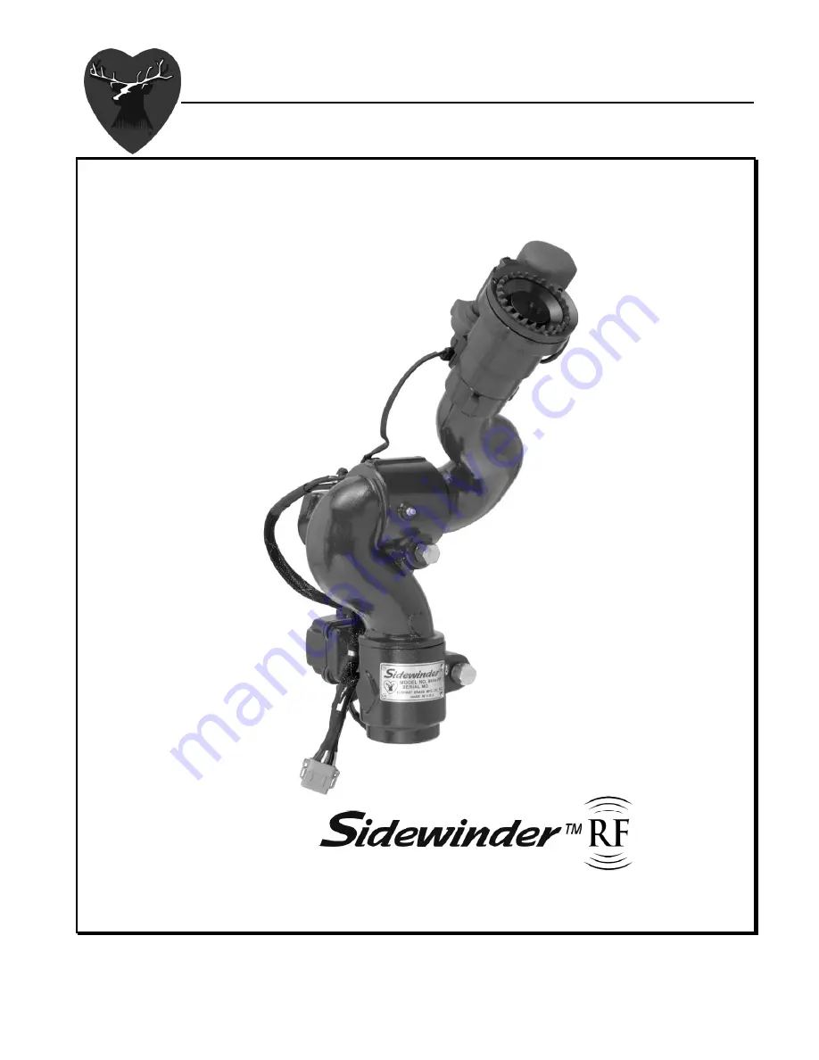
Installation, Operating,
& Maintenance Instructions
8494
Monitor