background image

Radio

Adapter

Pag. 10/12

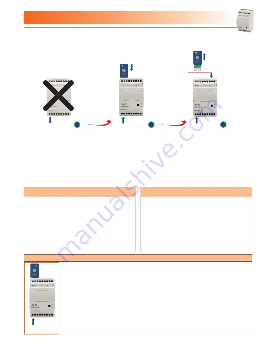
3.1 - REPLACING THE PAN-C

When a PAN-C is found to be faulty, replace it with a new RadioAdapter.
Follow the steps below when replacing a faulty PAN-C with a new one.

Power 

Supply

Power 

Supply

Power 

Supply

Supervisor

1

2

3

1 - Disconnect and remove the faulty
     PAN-C.

2 - Place a new 

Radio

Adapter in the

     place of the PAN-C just removed.

     Set the switch on the 

Radio

Key to

     position 5.

     Connect the 

Radio

Key to the


Radio

Adapter and wait for the

     YELLOW LED (P) on the 

Radio

Key

     to light up. 

3 - Disconnect the 

Radio

Key and

     connect the new PAN-C to the 
     network

3.2 - REPLACING A NODE

3.3 - REPLACING A DEvICE

When a NODE is found to be faulty, the component must be
replaced with a new 

Radio

Adapter.

Follow the steps below when replacing a faulty NODE with a 
new one:
  - Disconnect and remove the faulty NODE.
  - Place a new 

Radio

Adapter in the place of the NODE you

    removed.
  - Install and configure the new NODE following the steps
    outlined in section “

How to install a NODE

”.

  - Repeat the PAN-C configuration as described in section 2.4
    Configuring the PAN-C

Follow the steps below when replacing a faulty device with a new
one:

- if the new device has the same address (Televis or Modbus) as
  the old one, just connect it to the NODE.

- if on the other hand the new device has a different address
  (Televis or Modbus) from the old one, the respective NODE will
  have to be Reset (see section “

Resetting a NODE

”)

3.4 - RESETTING A NODE

Power 
Supply

- Disconnect the device from the NODE.

- Set the switch on the 

Radio

Key to position 1.

- Connect the 

Radio

Key to the NODE and wait for the GREEN LED (N) on the 

Radio

Key to light up.

  The NODE has now reset.

- Disconnect the 

Radio

Key and configure the NODE following the steps outlined in sections “

Address

  configuration and searching for connected devices

“ and “

Saving settings

”.

3 - TROUbLESHOOTING

Summary of Contents for RadioAdapter

Page 1: ...RadioAdapter MANAGEMENT AND MONITORING ISM 2 4 GHz wireless system for plant monitoring and control USER MANUAL...

Page 2: ...2 2 3 Saving settings 7 2 3 How to install a repeater 8 2 3 1 Initializing a repeater 8 2 3 2 Self configuring a repeater 8 2 3 3 Saving repeater settings 8 2 4 Configuring the PAN C 9 2 4 1 Transferr...

Page 3: ...against harmful interference when the equipment is operated in a commercial environment This equipment generates uses and can radiate radio frequency energy and if not installed and used in accordanc...

Page 4: ...1 5 Installing the antenna NO FCC models The antenna can be inserted straight into the RadioAdapter connector or panel mounted and connected to RadioAdapter using the cable supplied in the Antenna ki...

Page 5: ...e 19200 bps parity odd stop bit 1 CCA0B0T01M500 RadioKey Modbus bit rate 19200 bps parity none stop bit 1 NOTE The features described in this table depend on the value of the 11th digit of the RadioKe...

Page 6: ...is now configured as PAN C and all PAN C information is sent to the RadioKey From now on the RadioKey can only be used with this network We recommend you mark this RadioAdapter with the sticker suppli...

Page 7: ...gs Power Supply Power Supply Power Supply TTL RS485 Configure the Televis or Modbus address of the devices to be connected to the NODE Connect the devices to the NODE via TTL or RS 485 Switch on the d...

Page 8: ...TER The GREEN LED on the repeater will now start to blink fast 2 3 2 Self configuring a repeater 2 3 3 Saving repeater settings Power Supply Power Supply Disconnect the RadioKey from the repeater Wait...

Page 9: ...NOTA Communication between NODES repeaters and PAN C and the monitoring device will commence after at least 1 minute has passed after each component of the network was switched on 2 5 Changes to netwo...

Page 10: ...NODE Place a new RadioAdapter in the place of the NODE you removed Install and configure the new NODE following the steps outlined in section How to install a NODE Repeat the PAN C configuration as de...

Page 11: ...on Saving repeater settings Power Supply Power Supply 1 2 3 5 2 Setting communication channel manually Power Supply Power Supply Power Supply PAN C PAN C NODE Power Supply NODE 1 2 3 4 OTHER NODES 1 S...

Page 12: ...ithout notice 4 3 RESPONSIBILITY AND RESIDUAL RISKS ELIWELL CONTROLS SRL shall not be liable for damage resulting from Installation uses other than those specified and in particular which do not compl...

Reviews: