background image

USER INTERFACE

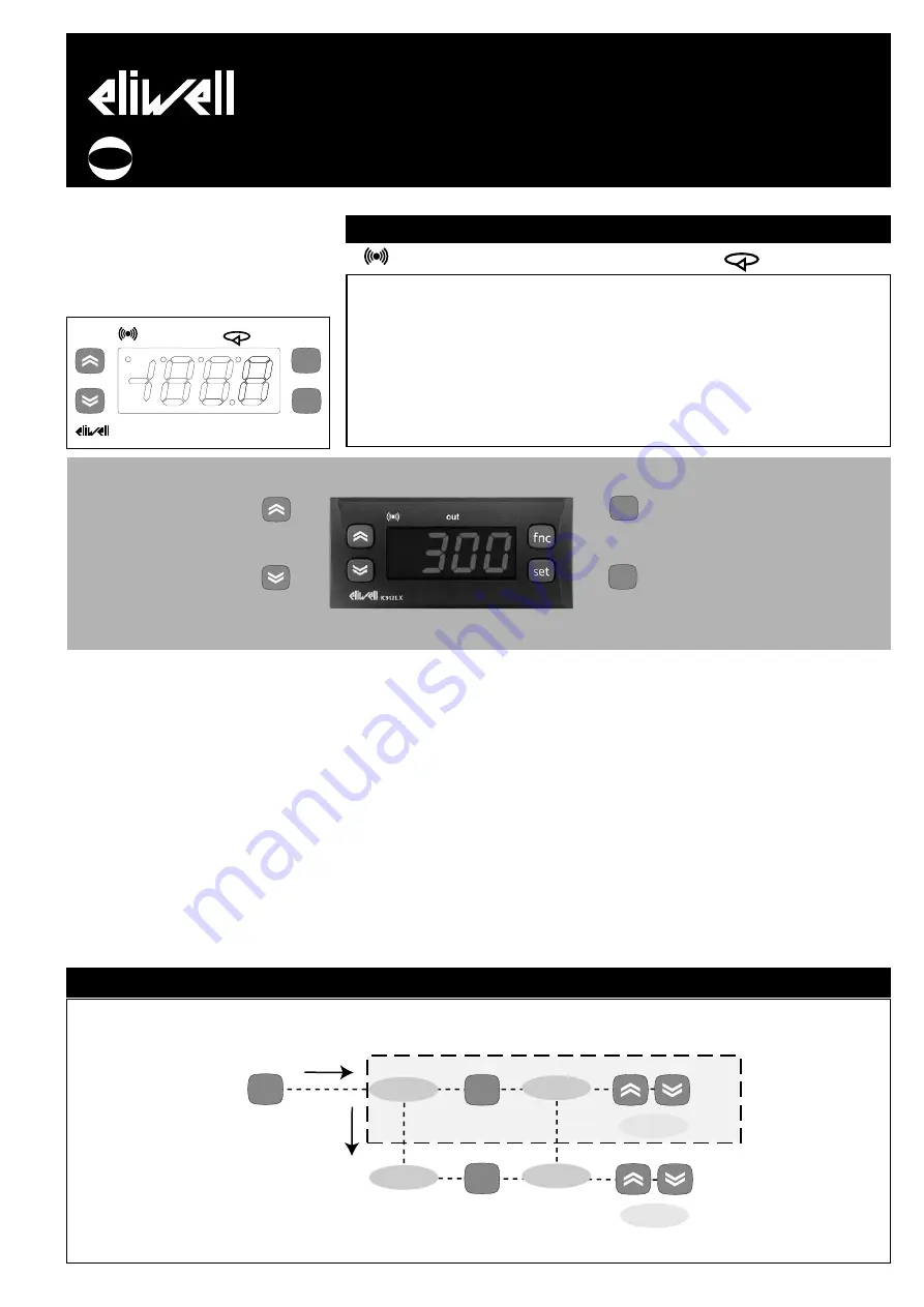
The user has a display and four keys for
controlling status and programming of the
instrument.

DISPLAY

KEYS AND MENUS

At start-up the instrument performs a
Lamp Test; for five (5) seconds the display
and the leds blink, in order to verify their
integrity and correct operation; afterwards
it will appear the label “Lod” (Loading) for
ten (10) seconds. The instrument has two
main menus: the “Machine Status” and
“Programming” menu.

ACCESSING AND USING MENUS

The resources are arranged in a menu that
can be accessed by pressing and quickly
releasing the “set” button (Machine Status
menu) or holding down the “set” button
for more than 5 seconds (Programming
menu). 
To access the contents of each folder indi-
cated by the relevant label, just press the
“set” button once. 
You can now scroll through the contents
of each folder, modify it or use its func-
tions. If you do not use the keyboard for
over 15 seconds (time-out) or if you press
the “fnc” button once, the last value
shown on the display is confirmed and
you are taken back to the previous screen 

MACHINE STATUS MENU
(See Machine Status Menu Diagram)

To access the Machine Status menu, press
the “set” button and quickly release it. 
The “SP1” label appears. 
(If alarms are active, with the exception of
faulty probes/probe errors, the “AL” label
appears). 
By using the “UP” and “DOWN” buttons
you can scroll through the other folders in
the menu: the folders are indicated below
in the order they appear: 
-SP1: Set point 1 setting folder or
-AL: alarm folder (if alarms present, with

exception of faulty probes/probe errors);

-Pb1: probe 1 value folder;

IC 912 LX Pt100°R

electronic controller with single output 
and regulation in Réaumur degrees

set

f nc

IC912LX

out 

cod. 9IS23094

rel. 11/04

GB

AL

SP1

set

alarms

SP1 value

set

set

t

change

SP1 value

show alarms

press and release

(single press)

if alarm(s)

 present

MACHINE STATUS MENU DIAGRAM

Scrolls through the menu items

UP button

Increases the values
Parameter programmable 
(par. H31)

DOWN button

Scrolls through the menu items
Decreases the values
Parameter programmable
(par. H32)

fnc button

ESC function (quit) 
Parameter programmable 
(par. H33)

Set point button

1-Accesses Machine Status Menu
(SET POINTS, ACTIVE ALARMS,
PROBE READING) and labels/values;
1-Accesses Programming Menu
(PARAMETERS, COPY C ARD) and
relative labels/values; 
3-Confirms commands
4-Activates the functions*

fnc

set

Alarm 

•ON

for active alarm;

•blinking

when a silenced alarm is

still present

out1

Relay 1 (OUT1)

• ON

for relay on (energized);

•blinking

for protection delay or

enabling blocked

Soft Start / Setpoint

• 

ON

when Set point is being set

• 

blinking

when

Soft Start function is on

Set-point/ Reduced set point

•ON to modify Set-Point;

•blinking when reduced set point

is entered

LED

out1

Summary of Contents for IC 912 LX Pt100 R

Page 1: ...probe errors the AL label appears By using the UP and DOWN buttons you can scroll through the other folders in the menu the folders are indicated below in the order they appear SP1 Set point 1 setting folder or AL alarm folder if alarms present with exception of faulty probes probe errors Pb1 probe 1 value folder IC 912 LX Pt100 R electronic controller with single output and regulation in Réaumur ...

Page 2: ...ing parameters to the instrument NOTE UPLOAD instrument Copy Card DOWNLOAD Copy Card instru ment The operations are performed by access ing the folder identified by the FPr label and selecting the UL dL or Fr commands The operation is confirmed by pressing the set button If the oper ation is successful a y is displayed whereas if it is unsuccessful an n will be displayed Download from reset Connec...

Page 3: ...tton and the value 0 will appear enter the password using the UP DOWN buttons and press the set button again This allows you to access the level 2 parameters The first folder that appears is CP NOTE At this level the folders will only display all the level 2 parame ters Therefore level 1 parameters will only be visible if you quit the Programming Menu and repeat proce dure 1 NOTE It is strongly re...

Page 4: ... label on the instrument Buzzer output only on models with Buzzer Measuring range from 150 to 1350 Accuracy 0 5 for all scale 1 digit 0 2 from 120 to 240 C Resolution 0 1 R within 199 9 C 1 R over Consumption model 230V 3 VA max model 12 24V 1 5 VA max Power supply 12 24 Va c 10 or 230Va 10 50 60 Hz Warning check the power supply specified on the instrument label for relay and power supply capacit...

Page 5: ...ART function ALARMS folder with AL label Alarm type Parameter HA1 and LA1 modes as temperature absolute values or as differential compared to the Setpoint 0 absolute value 1 relative value Alarm Fan differential Alarm differential Power on Alarm Override Alarm exclusion time after instrument switch on after a power failure Setpoint Alarm Override Exclusion alarm time until Setpoint is reached 0 di...

Page 6: ...from power on WARNING If set 0 it is not active if set 0 output will not be activated before this time Configuring digital inputs 0 disabled 1 SOFT START 2 Offset Setpoint 3 outputs stopped 4 not used 5 auxiliary output 6 stand by 7 maintenance requested 8 external alarm 9 external alarm stop regulators Polarity and Priority Digital Input no normally open nc normally closed noP normally open with ...

Page 7: ...ulators if speci fied by the H11 9 parameter This alarm condition can be viewed in the AL folder with the label EA The relay can be silenced even if alarm icon starts blinking controls stay locked until the next time the digital input is deactivated DIAGNOSTICS DISPLAY E1 FAULT Faulty probe 1 thermostat control Table of faulty probes DISPLAY AH1 AL1 EA Opd Press any button to silence the alarm The...

Page 8: ...ustomer Support Email techsuppeliwell invensys com Telephone 39 0437 986300 Climate Controls Europe An Invensys Company 11 2004 eng cod 9IS23094 SP1 SP1 dF1 dF1 Off On HC1 H SP1 dF1 SP1 dF1 Off On HC1 C HC1 Heat Cool Mode SP1 Setpoint 1 dF1 diFferential Relay 1 tripping differential ON OFF REGULATION DIAGRAM RS232 to PC RS485 BusAdapter PCInterface TTL PC with Televis package 230V N L 230V N L The...

Reviews: