P6EX-A+ User’s Manual
3:
Reconfiguring Your Mainboard – 3.6
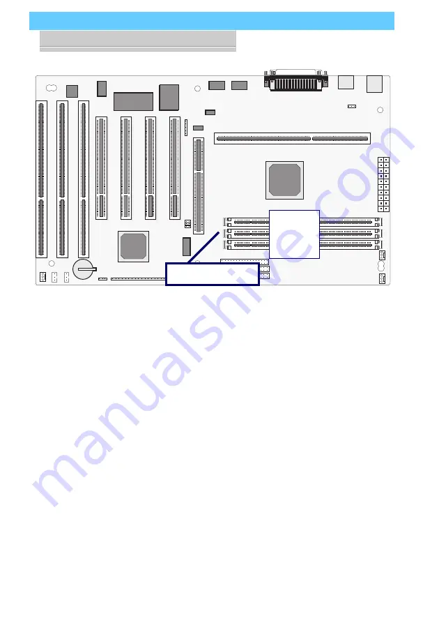
DIMM1
DIMM2
DIMM3
DIMM Sockets
The picture above shows the
memory module sockets in
detail. The sockets are num-
bered DIMM1 and DIMM2
starting from the upper socket
in the picture.
Modules press into place
and are held in position by a
retaining clamp at each end
of the socket.
When you want to remove a
module, press down on the
retaining clamps to push the
module out of the socket.
Retaining Clamp


