background image

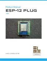
Product manual : ESP-12 Plug 


Elint Labz (

www.elintlabz.in

                                                                                                      Page 11  of  11


Summary of Contents for ESP-12 PLUG

Page 1: ...Product Manual ESP 12 Plug Updated on 27th November 2017...

Page 2: ...Product manual ESP 12 Plug Index About Elint Labz 2 Introduction 3 Specification 3 Operating voltage 5V 3 Variants 3 Supported cables 3 Details 3 Elint Labz www elintlabz in Page 1 of 11...

Page 3: ...ons in which scientific or technological research experiments and measurement may be performed EL is an enterprise built to develop smart intelligent electronics EL is committed to help achieve electr...

Page 4: ...e easily mounted anywhere using the screws Specification Operating voltage 5V Size 27mm x 30mm Variants None Supported cables 4 4 A Details This Module is a simple solution for interfacing ESP8266 wit...

Page 5: ...g The pins of ESP8266 can be directly connected to the breakout board It consists of 16 pins They are vcc pin ground pin reset pin adc pin transmitter pin receiver pin and 9 GPIO pins Elint Labz www e...

Page 6: ...al ESP 12 Plug The GPIO pins are 0 2 4 5 12 13 14 15 and 16 The breakout board also consists of 3 male ports for enabling configuring and interfacing serial communication Elint Labz www elintlabz in P...

Page 7: ...Product manual ESP 12 Plug The breakout board can be easily mounted on a breadboard or any other controller Elint Labz www elintlabz in Page 6 of 11...

Page 8: ...cation port consists of 4 pins they are Tx pin Rx pin vcc pin and gnd pin The configuration port consists of the GPIO pin zero If a high signal is given to the pin then the chip will be in configure m...

Page 9: ...signal given is low then the chip will be in running mode The enable port consists of CH_PD pin which is used to enable the chip If the signal given to the pin is high then the chip is enabled Elint L...

Page 10: ...Product manual ESP 12 Plug To disable the chip a low signal should be given to the in pin CH_PD Elint Labz www elintlabz in Page 9 of 11...

Page 11: ...nect one end of the cable to wifi breakout and the other end of the cable to the serial port on the pluguino board Make sure that black wire is connected to ground pin on both the sides The below give...

Page 12: ...Product manual ESP 12 Plug Elint Labz www elintlabz in Page 11 of 11...

Page 13: ...Product manual ESP 12 Plug The below given picture shows the interfacing of Wifi breakout with the USB to Serial Converter Elint Labz www elintlabz in Page 12 of 11...

Reviews: