background image

Elimko 

E-PR-200


KY-PR200-0420-0 


PAGE 

38/56


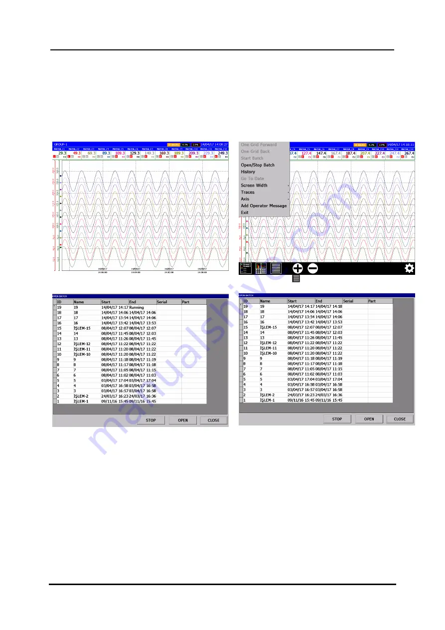
The transaction table for each group is separated. If the 

Trend Page

 is displayed in which group, the process 

table of that group can be displayed. When the 

Trend Page

 of the relevant group is selected, the running 

processes and previously completed processes can be displayed by pressing the button (

see Figure 6.59, 

Figure 6.60, Figure 6.61 and Figure 6.62

). Trend can be watched by selecting a previously completed 

process and pressing 

Open

. The Stop key 

Stops

 the selected operation if it is running. The system 

automatically restarts with a new transaction number even if the operation that is activated by the digital 
input is stopped. 


Figure 6.59 For example,  GROUP-1 Trend Page 


Figure 6.60 Press 

 to select Open/Stop Batch 


Figure 6.61  GROUP-1 Page, Open Batch 


Figure 6.62 GROUP-1 Page, Stop Batch 

Summary of Contents for E-PR-200 Series

Page 1: ...ATIC CONTROL SYSTEM AND TURN KEY CONTRACTS Manufacturer Technical Support Elimko Electronic Production and Control Co Ltd 8 Avenue 21 Street No 16 06510 Emek Ankara TURKEY Phone 90 312 212 64 50 Fax 9...

Page 2: ...6 CHANNELS PAGE 24 6 6 1 RELAY OUTPUT CARD ADJUSTMENTS 24 6 6 2 DIGITAL OUTPUT CARD ADJUSTMENTS 25 6 6 3 ANALOG INPUT CARD ADJUSTMENTS 25 6 6 4 ANALOG OUTPUT CARD ADJUSTMENTS 27 6 6 5 ALARM ADJUSTMENT...

Page 3: ...utput Card Calibration Page 22 Figure 6 11 Hardware Ethernet Page Obtain an IP address via DHCP 22 Figure 6 12 Hardware Ethernet Page Manual Set 22 Figure 6 13 Hardware Serial Port screen 23 Figure 6...

Page 4: ...6 64 Analog Input page table selection 40 Figure 6 65 Archive Synchronization Page 41 Figure 6 66 Archive Backup Page 41 Figure 6 67 E MAIL Server Page 41 Figure 6 68 E MAIL Recipients Page 42 Figure...

Page 5: ...dor from which you purchased the product Before installing and operating the controller please read the user manual thoroughly The installation and configuration of the recorder must only be performed...

Page 6: ...annels Up to 32 Digital Output Channels Up to 18 Analog Output Channels Standard RS 485 communication port 10 100 Mbit Ethernet Port Wi Fi Optional USB Host Port 4 1 TYPE CODING E PR 200 S1 S2 S3 S4 S...

Page 7: ...uts Max 54 Analog Inputs 16 bit isolation of channels 1000 V AC See Section 7 CONNECTION DIAGRAMS Analog Outputs 0 20 mA 0 10 V can be configured Number of analog outputs is limited to 18 Digital Inpu...

Page 8: ...a suitable grounded metal enclosure panel This must prevent the live parts being accessible to human hands and metal tools See Section 7 CONNECTION DIAGRAMS E PR 200 does not include a power switch Th...

Page 9: ...ea appears in blue see Figure 5 1 Figure 5 1 Trend View During normal operation the operation buttons are hidden to increase the display area Hidden operation buttons can be made visible by touching t...

Page 10: ...etailed explanations of the menus are given in the related description of the views This button is active only in the trend view Used to increase or decrease the width of the screen This button allows...

Page 11: ...ed in Operator Menu While in history mode process values date and time seen on the screen are the values at the time of cursor location By touching the screen the location of the cursor can be changed...

Page 12: ...can be chosen with this parameter Desired traces can be opened or closed in Traces Menu Axis The axis of the channel to be seen on the trend can be chosen with this parameter Add Operator Message Add...

Page 13: ...rm states of 12 channels in selected group are viewed Channel Name Process Value Alarm 1 Alarm 2 If the alarms are defined H or L is written according to alarm types Active alarms are shown with red c...

Page 14: ...Digital View Page Operator Menu for Digital View Page is opened by pressing button To reset the totalizer of an individual source select the corresponing source name in sub menus of Reset Totalizer m...

Page 15: ...upy two rows and due to overall row limitation some of the process groups appears intermittently 5 6 Alarm Log Figure 5 11 Alarm Log screen The last occurred and released 10000 alarms with date and de...

Page 16: ...lizer is displayed at the top of the list Totalizer values can be scrolled by and buttons The time intervals of totalizers are defined with the Logging Source parameter of related Totalizer 5 8 Instru...

Page 17: ...r Log Page and keys scrolls the page up and down direction see 5 2 TREND PAGE ve 5 4 DIGITAL VIEW PAGE 5 10 Digital Log Figure 5 15 Digital Log screen Source Name record date and definition of the las...

Page 18: ...reached by either pressing MENU or LOGIN button LOGIN access does not require authentication on subsequent entries until LOGOUT is pressed from Main Menu Depending on previously defined authorization...

Page 19: ...nication Addresses see Appendix 3 Figure 6 2 Main Menu 6 3 Device Page Figure 6 3 Device Page In Device Page Device Type and Version are shown Date and Time adjustments and factory settings reset are...

Page 20: ...ware Page The hardware adjustments are made in this page HARDWARE Page consists of 4 tabs as Slot Ethernet Serial Port and Screen 6 5 1 Slot Adjustments ATTENTION The calibration parameter adjutment r...

Page 21: ...ation Figure 6 9 Analog Input Card Calibration Page 50 mV Set the calibrator as a millivolt source and adjust the calibrator output 50 000 mV Apply the calibrator output to the millivolt input of the...

Page 22: ...value of the calibration is set using the up and down keys For ease of calibration up and down keys are given as two pieces of 100 levels and 10 levels 100 steps for coarse changes 10 steps are used...

Page 23: ...of the screen Brightness can be adjusted between 20 and 100 Screen Saver ON or OFF selectable Screen Saver Time Determines the time period after that the device starts screeen saver if no operation ta...

Page 24: ...d Relay Output can be written by this parameter maximum length of 12 characters Description Maximum 50 characters long description Off Message Maximum 100 characters long alarm off message On Message...

Page 25: ...to linearize the Linear Inputs while the process value is calculated Decimal Point Determines the position of decimal point The parameter can be adjusted as 0 0 0 0 00 or 0 000 Zero Span Determines p...

Page 26: ...Thermocouple Figure 6 23 Linearization Select Input Type Resistance Thermometer Figure 6 24 Linearization Select Input Type Ohm Milivolt Miliamper or Volt ATTENTION CJ Type CJ Source and CJ temperatur...

Page 27: ...med with using maximum 12 character Description Maximum 50 characters long description Source Determines the analog source by which the analog output is controlled Type Output type mA or Volt can be s...

Page 28: ...IGH alarm types deviation for SLOW RATE and FAST RATE types Hysteresis Defines alarm hysteresis for LOW and HIGH alarms Latch Enable Enabling latch causes alarm on state to persist until being acknowl...

Page 29: ...is defined for each slot analog input math analog and Modbus analog channels Name Totalizer of related channel can be named with using 12 characters Enable Determines if totalizer is active or not Per...

Page 30: ...ach recording period option certain number of sampled values are collected depending on selected recording period Total Number Of Samples Recording Period ms 100 Filter parameter determines the way ho...

Page 31: ...d recording settings 6 6 9 Modbus Channels Page Up to 16 MODBUS RTU channels can be configured by this page Firstly channel number is clicked from the left of the screen before starting the configurat...

Page 32: ...Decimal Point Determines the position of decimal point The parameter can be set as 0 0 0 0 00 or 0 000 Fault Value Determines the value of the channel in fault status Unit Determines the unit Figure...

Page 33: ...e related real time source will be active as shown below For example if Period Start and End are adjusted as Every Minute 0 5 respectively the related channel will be active in first 5 seconds of ever...

Page 34: ...on direction can be changed by selecting Horizontal Vertical and Circular Batch Start Input The desired group is selected from 12 groups Batch Start Input of the selected group can be defined Sources...

Page 35: ...nu Graphic Type Horizontal Vertical or Circular can be selected from the Groups menu see Figure 6 50 Figure 6 51 Figure 6 52 and Figure 6 53 show the graphical representation of the Graphic Type selec...

Page 36: ...w process This process continues as long as the digital input is active and the process is stopped by recording the interruption of the digital input When entered into the GROUPS menu the Batch Start...

Page 37: ...s activated Figure 6 57 shows the passivation status of the digital input and Figure 6 58 shows the case where the process number is incremented and the new process is started when the digital input i...

Page 38: ...by pressing the button see Figure 6 59 Figure 6 60 Figure 6 61 and Figure 6 62 Trend can be watched by selecting a previously completed process and pressing Open The Stop key Stops the selected operat...

Page 39: ...420 0 PAGE 39 56 The data stored in the device can be downloaded to the computer via USB or ETHERNET connection with the E PR 200 DATA EXPLORER program and the printer output can be retrieved A sample...

Page 40: ...to delete all stored data archives Resetting archive causes all records to be lost irreversibly Sync Direction Sync Direction determines synchronization direction DEVICE TO DISC option transfers the...

Page 41: ...by multiple configurable triggers such as sources and general events 6 11 1 Server Adjustments Server SMTP incoming mail server Port SMTP port number SSL Disable or Enable SSL User User Account Name P...

Page 42: ...ed to any of the sources Figure 6 69 E MAIL Sources Page 6 11 4 Events On New Alarm ON or OFF selectable If ON is selected a new e mail is sent when an alarm occurs On New Instrument Log ON or OFF sel...

Page 43: ...ce name Description Maximum 50 characters can be entered Additional explanation can be entered Input Source Determines PID control loop input variable the process variable to be controlled The input s...

Page 44: ...ll affect the process variable should be in mind For instance cooling outputs causes a reverse reaction of temperature output Proportional Band Proportional band of PID loop in engineering unit Integr...

Page 45: ...Value on TREND view screen and click PID Source on the BAR or DIGITAL view screen to open the PID CHECK window By using the set value arrows from the opened window you can change it by entering set v...

Page 46: ...ice and used for different purposes Profile sources can be assigned as external set source for PID channels in the device Profile sources can be transmitted to other systems as reference sources using...

Page 47: ...Elimko E PR 200 KY PR200 0420 0 PAGE 47 56...

Page 48: ...Elimko E PR 200 KY PR200 0420 0 PAGE 48 56 ekil 6 78 6 13 1 Curves Explanations about the parameters are given below The screenshot is as given in Figure 6 79 ekil 6 79...

Page 49: ...the desired card fix the screws again During changing or adding card device should be powered off After each new card configuration it must be registered by scanning new configuration Please see Secti...

Page 50: ...Card Connection Diagrams 6 Channels RT ohm For TC input E CJ NTC 01 terminals supplied with the device seperately should be used Up Down 1 Channel 2 Channel 3 Channel Up Down For TC input E CJ NTC 01...

Page 51: ...short circuited with a suitable cable Snubber consist of serially connected a capacitor 10nF 630 V and a resistance 100 1 4 W and can be used to suppress the contact noise While the contact is used fo...

Page 52: ...All registers given in Appendix 3 can be read or write depending on access rights 5 Barcode Scanner Connection Please check Appendix 4 for detailed explanation 6 Wi Fi Indicates that the Wi Fi connec...

Page 53: ...sing OK key saves the equation CANCEL key cancels all operations Script is defined in the key device used for the incorporation of equality of a team ready to function When pressed Script out the foll...

Page 54: ...Addresses Modbu RTU Register addresses can be reached from MODBUS TABLE window by presing the MODBUS TABLE button in the Main Menu Digital channel grouped by slots are respresented with a single addre...

Page 55: ...Elimko E PR 200 KY PR200 0420 0 PAGE 55 56...

Page 56: ...e operations are Start Batch Stop Batch and Batch Name Input Barcode scanner should be configured as an USB keyboard emulator and barcode termination character should be set to horizontal tab ASCII 9...

Reviews: