5
Installation and Commissioning
64
5.6 Electrical Connection
The text below describes electrical connection of the corrector with other devices. For the
described connections to work properly, the device should also be set correctly up. The device
can be set up either using the service software [42], [43] or from the device keypad (see Section
5.6.1 Connecting Cables
Always use shielded cables complying with the standard [10] to connect the
device to other devices.
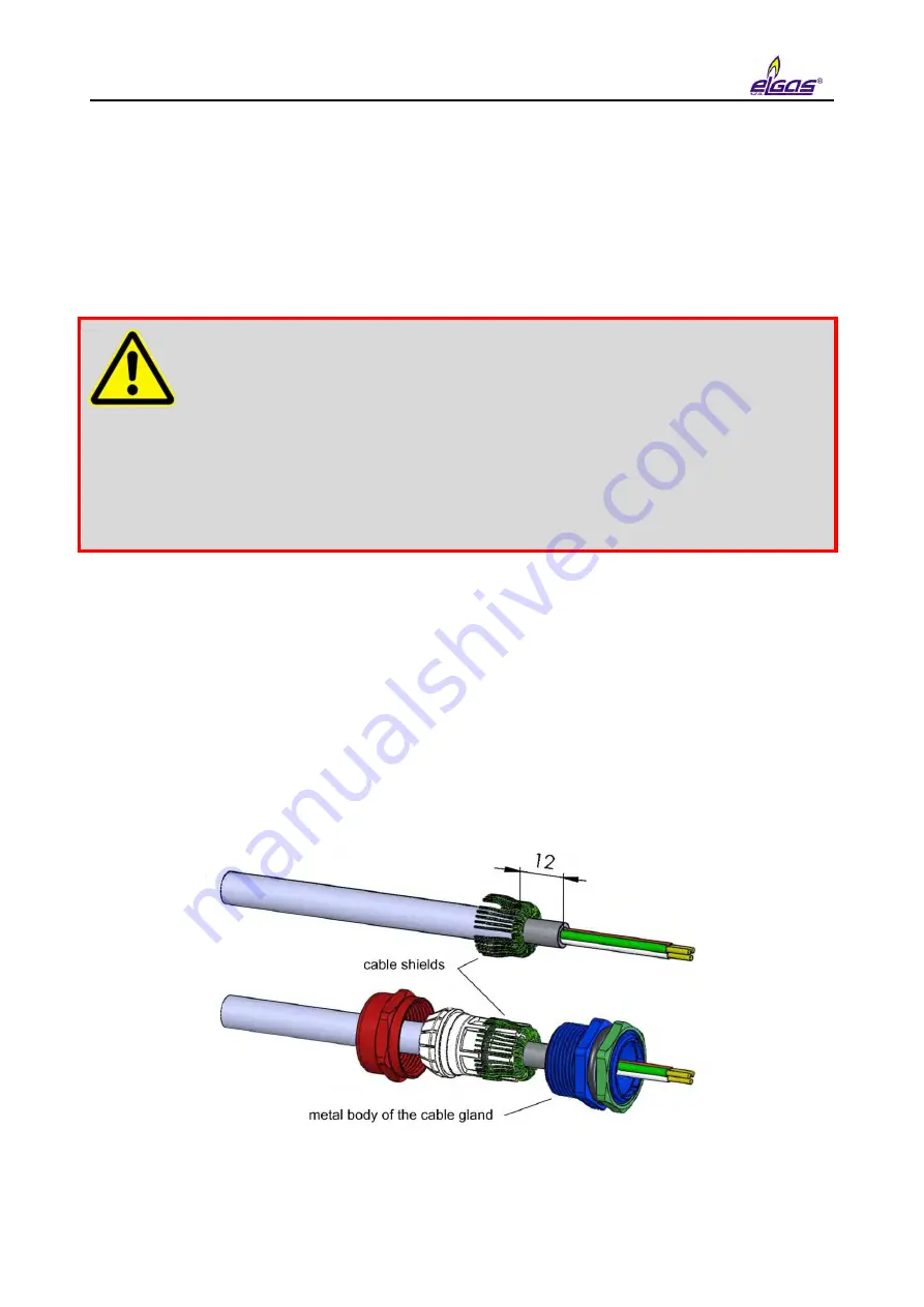
On the device side, the shields of all the connected cables must be
connected to the metal body of the cable gland according to
When installing the device and connecting the cable shields, make sure that
ground loops are not created.
All the cable glands in the device are electrically interconnected, the shields of all
the cables entering the device are therefore connected at this point. This ensures
high resistance to electromagnetic interference.
The following applies:
For the digital pressure transducer (i.e. built into body of the device housing), the
metal housing of the transducer is conductively connected with the metal cable
glands of the device, i.e. with the shielding of the cables fixed in the cable glands of
the device.
The temperature transducer and the external digital pressure transducer (if
installed) are connected to the device with a shielded cable whose shield is
connected to the metal body of the cable gland.
The metal shank of the temperature transducer is insulated from the shield of the
cable and all other parts of the device.
The metal body of the external pressure transducer is connected to the cable
shield.
Fig. 20 Connecting the cable shields in the cable glands
Summary of Contents for DATCOM
Page 38: ...3 Technical Parameters 36 ...
Page 50: ...5 Installation and Commissioning 48 Fig 7 Examples of data plates ...
Page 83: ...5 Installation and Commissioning 81 Fig 37 Communication via RS232 RS485 using B RS module ...
Page 115: ...7 Technical Description of the Device 113 Fig 57 Functional diagram of ELCOR ...
Page 116: ...7 Technical Description of the Device 114 Fig 58 Functional diagram of ELCORplus ...
Page 122: ...7 Technical Description of the Device 120 Fig 61 Modem replacement ...
Page 159: ...10 Communication with the Device 157 packet ...
Page 174: ...12 Accessories 172 Fig 78 ELCORplus example of use of external modules ...
Page 213: ...Appendix 3 Compass Data Export 211 Preview of generated document ...
Page 215: ...Appendix 3 Compass Data Export 213 3 Export to XLS 4 Export to TXT DOC ...
Page 216: ...Appendix 3 Compass Data Export 214 ...
Page 217: ...Appendix 3 Compass Data Export 215 5 Export of graph ...


