Elenco Electronics K-26 Assembly And Instruction Manual Download Page 6

-5-

SCHEMATIC DIAGRAM

PC BOARD FOIL SIDE

TROUBLESHOOTING

Contact Elenco

TM

Electronics if you have any problems.

DO NOT contact your place of purchase as they will

not be able to help you.

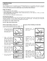
1. One of the most frequently occurring problems is

poor solder connections.

a) Tug slightly on all parts to make sure that

they are indeed soldered.

b) All solder connections should be shiny.

Resolder any that are not.

c) Solder should flow into a smooth puddle

rather than a round ball.

Resolder any

connection that has formed into a ball.

d) Have any solder bridges formed?  A solder

bridge may occur if you accidentally touch
an adjacent foil by using too much solder or
by dragging the soldering iron across
adjacent foils. Break the bridge with your
soldering iron.

2. Be sure that all components have been mounted

in their correct places.

a) Use a fresh 9V battery.

b) Be sure that the coil is soldered properly.

The two ends of the wire should be clear of
insulation, so that the solder can make good
contact with the wire.

c) Your most likely problem will be tuning the

metal detector oscillator to the radio. Start
at around the 1,000kHz spot on the radio.
Pick a spot that is clear of radio stations. You
should hear only static.

Rotate the

potentiometer P1 very slowly until the static
gets quiet.

If you cannot quiet the radio,

tune the radio to a higher frequency, around
1,300kHz and try adjusting the
potentiometer again. If still no luck, try a
lower frequency, around 700kHz.

You

should be able to find a spot when the metal
detector oscillator has an effect. Moving a
piece of metal around the coil should
produce changes in the sound from the
radio.

Summary of Contents for K-26

Page 1: ...reserved Revised 2003 REV D 753226 No part of this book shall be reproduced by any means electronic photocopying or otherwise without written permission from the publisher METAL DETECTOR KIT MODEL K 2...

Page 2: ...1 S1 Switch 541102 1 Solder Roll 24 551124 1 B1 Battery Snap 9V 590098 1 Wire 26 Enamel 45 846000 1 Resistor Transistor Capacitor PARTS IDENTIFICATION Switch Discap Battery Snap Trim Pot IDENTIFYING...

Page 3: ...illate at the LC resonance frequency By varying P1 the current through transistor Q1 will change thus forcing the frequency of the oscillator to change slightly Figure 1 C1 C2 R2 R1 B1 S1 Q1 P1 L1 THE...

Page 4: ...mponent Lead Solder Soldering Iron Drag Foil 1 Solder all components from the copper foil side only Push the soldering iron tip against both the lead and the circuit board foil 2 Apply a small amount...

Page 5: ...Coil see Figure B C2 0015mF Capacitor 152 S1 Switch B1 Battery Snap Install the red wire into the positive hole and the black wire into the negative hole Solder and cut off the excess leads R2 4 7kW 5...

Page 6: ...bridge with your soldering iron 2 Be sure that all components have been mounted in their correct places a Use a fresh 9V battery b Be sure that the coil is soldered properly The two ends of the wire...

Page 7: ...n LC circuit has a coil and a ___________ 7 An inductor can be made by winding some wire into a ____________ 8 If part of the energy in the LC circuit in Figure 1 is fed to the emitter of Q1 the circu...

Page 8: ...ElencoTM Electronics Inc 150 W Carpenter Avenue Wheeling IL 60090 847 541 3800 http www elenco com e mail elenco elenco com...

Reviews: