


13
Z2
U2
U1
Z1
L1 N
L1 N
Z2
U2
U1
Z1
W2
U2
V2
U1
V1
W1
W2
U2
V2
U1
V1
W1
(L3) (L1)
(L3) (L1)
L1 L2 L3
L1 L2 L3
Operating and assembly instructions SD
www.elektror.com
9016312 01.20/09
EN
the motor terminals with longer cables, higher
frequency converter supply voltages and/or if
the pulse voltages are exceeded (max. 1000 Vpk
for drive motors up to 0.75 kW, maximum 1300
Vpk for drive motors larger than 0.75 kW). Please
contact the converter supplier in this case. If a
motor
fi
lter is included in the delivery, this must
be installed between the converter and the motor.
Please ensure that there is su
ffi
cient space in the
switch cabinet and take into account the installa-
tion and assembly requirements in the operating
instructions of the frequency converter/motor
fi
lter manufacturer.
• The wire running between the motor and the
frequency converter must not exceed a length of
20 m, con
fi
gured as a suitable, shielded cable
and laid by as direct a route as possible, without
any additional plug/clamp connections.
• The braided screen in the connecting cable
must cover the full length of the cable on both
sides, i.e. be connected to the earthing system at
the frequency converter and to the motor using a
low electrical resistance. For this purpose, suit-
able EMC cable couplings must be used on the
motor side. They must contact the cable shield
around its full circumference and have a low
resistance.
For further information about EMC compliant installation and
assembly, refer to the Operating and Assembly Instructions
issued by the frequency converter manufacturer.
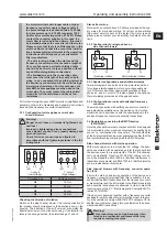
3.3.1 Con
fi
guration for three-phase current side
channel
blowers
Warning!
Danger due to loose or improperly tightened con-
nections!
Improperly tightened and loose connections
cause electric shocks,
fi
res, property damage and
personal injuries!
Check for loose connections and tighten in
accordance with the tightening torques in the fol-
lowing table.
-circuit
Y circuit
(low voltage)
(high voltage)
Threaded bolt
Tightening torque
M4
1,2 Nm
M5
2,0 Nm
M6
3,0 Nm
M8
6,0 Nm
Checking the direction of rotation
Switch on the side channel blower. The running direction of
the impeller should correspond to the direction arrow on the
housing. The direction of the air
fl
ow must also match the
directional arrows on the silencer housing. If the impeller ro-
tates in the wrong direction, then interchange L1 and L3.
Star-delta start-up
Motors with an output above 3.0 kW are provided at the sup-
ply mains for star-delta start-up. For direct on-line starting
(high short circuit current at the instant the motor is ener-
gised), please contact your local utility for details of condi-
tions.
3.3.2 Con
fi
guration for single-phase a.c.
side channel blowers
Clockwise rotation Anti-clockwise rotation
3.3.3 Special con
fi
gurations and additional clamps
Terminal diagrams can be found in the motor terminal box
for voltage interchangeable motors, pole-changeable mo-
tors, FU motors and other special con
fi
gurations of three-
phase a.c. and a.c. motors. This also applies to the optional
thermal winding protection and the space heater.
3.3.4 Con
fi
guration for units with attached frequency
converter
The mains connection with earthing conductor connection
and potential equalisation must be carried out in a profes-
sional manner in accordance with the speci
fi
cations in the
enclosed frequency converter assembly instructions.
3.4 Declaration concerning the EMC Directive
(2014/30/EU)
Our side channel blowers are components that are designed
to be installed in other machines or systems by quali
fi
ed per-
sonnel, i.e. not intended for consumers. The manufacturer
of the
fi
nal system/machine must guarantee/con
fi
rm that the
fi
nal system/machine complies with the EMC Directive.
Side channel blowers with mains operation:
With mains operation to a sinusoidal AC voltage, the asyn-
chronous motors with a squirrel-cage rotor that are built into
the devices meet the requirements of the EC “Electromag-
netic Compatibility” Directive 2014/30/EU, taking into ac-
count the standards EN 61000-6-4 (Emitted interference in
industrial environments) and EN 61000-6-3 (Emitted interfer-
ence in residential environments).
Side channel blowers with frequency converter opera-
tion (FU):
Prior to the start-up and during operation of the device on a
frequency converter (provided that this is suitable) it is es-
sential that the EMC instructions from the frequency convert-
er manufacturer and the information in the Elektror operating
and assembly instructions are observed in order to meet the
requirements of the EC “Electromagnetic Compatibility” Di-
rective 2014/30/EU.
If the device is delivered together with a frequency converter
package for switch cabinet or wall mounting closer to the mo-
tor, it is possible to comply with EN 61800-3 category C2 (In-
dustrial environments), taking into consideration the above-
mentioned EMC instructions.
Warning!
This product may cause high-frequency inter-
ference in a residential environment that may
require screening measures.


