background image

4

4

4

4

4

Important safety Instructions

READ AND SAVE THESE INSTRUCTIONS

Automatically Operated Device - T

Automatically Operated Device - T

Automatically Operated Device - T

Automatically Operated Device - T

Automatically Operated Device - To Reduce The

o Reduce The

o Reduce The

o Reduce The

o Reduce The

Risk Of Injury Disconnect Fr

Risk Of Injury Disconnect Fr

Risk Of Injury Disconnect Fr

Risk Of Injury Disconnect Fr

Risk Of Injury Disconnect Fr om Power Supply

om Power Supply

om Power Supply

om Power Supply

om Power Supply

Befor

Befor

Befor

Befor

Befor e Servicing.

e Servicing.

e Servicing.

e Servicing.

e Servicing.

TO  REDUCE  THE  RISK  OF  A  RANGE  TOP  GREASE
FIRE.

a)   Never leave surface units unattended at high settings.

Boilovers cause smoking and greasy spillovers that may
ignite.  Heat oils slowly on low or medium settings.

b) Always  turn  hood  ON  when  cooking  at  high  heat  or

when  flambeing  food  (I.e.  Crepes  Suzette,  Cherries
Jubilee, Peppercorn Beef Flambe’).

c) Clean ventilating fans frequently.  Grease should not

be allowed to accumulate on fan or filter.

d) Use proper pan size.  Always use cookware appropri-

ate for the size of the surface element.

TO REDUCE THE RISK OF INJURY TO PERSONS, IN

THE  EVENT  OF  A  RANGE  TOP  GREASE  FIRE,  OB-

SERVE THE FOLLOWING

:

a) SMOTHER  FLAMES  with  a  close-fitting  lid,  cookie

sheet, or other metal tray, then turn off the gas burner
or the electric element.  BE CAREFUL TO PREVENT
BURNS.  If  the  flames  do  not  go  out  immediately,
EVACUATE AND CALL THE FIRE DEPARTMENT.

b) NEVER  PICK  UP  A  FLAMING  PAN  -  you  may  be

burned.

c) DO NOT USE WATER, including wet dishcloths or tow-

els - a violent steam explosion will result.

d) Use an extinguisher 

ONLY

 if:

1) You know you have a class ABC extinguisher, and

you already know how to operate it.

2) The fire is small and contained in the area where it

started.

3) The fire department is being called.
4) You can fight the fire with your back to an exit.

OPERATION

a. Always  leave  safety  grills  and  filters  in  place. Without
these components, operating blowers could catch onto hair,
fingers and loose clothing.

The  manufacturer  declines  all  responsibility  in  the  event
of failure to observe the instructions given here for instal-
lation, maintenance and suitable use of the product. The
manufacturer  further  declines  all  responsibility  for  injury
due to negligence and the warranty of the unit automati-
cally expires due to improper maintenance.

Important safety Instructions

FOR GENERAL VENTILATING USE ONLY.  DO NOT USE
TO EXHAUST HAZARDOUS OR EXPLOSIVE MATERI-
ALS OR VAPORS.

TO REDUCE THE RISK OF FIRE, ELECTRIC SHOCK,

OR  INJURY  TO  PERSONS,  OBSERVE  THE  FOL-
LOWING:

A.

Use this unit only in the manner intended by the manu-
facturer.  If you have questions, contact the manufac-
turer.

B.

Before servicing or cleaning the unit, switch power off
at service panel and lock service panel disconnecting
means to prevent power from being switched on acci-
dentally.  When the service disconnecting means can-
not  be  locked,  securely  fasten  a  prominent  warning
device, such as a tag, to the service panel.

C.

Installation Work and Electrical Wiring Must Be Done
By Qualified Person(s) In Accordance With All  Appli-
cable  Codes  &  Standards,  Including  Fire-rated  Con-
struction.

D.

Sufficient air is needed for proper combustion and ex-
hausting  of  gases  through  the  flue  (Chimney)  of  fuel
burning  equipment  to  prevent  back-  drafting.  Follow
the  heating  equipment  manufacturers  guideline  and
safety standards such as those published by the Na-
tional  Fire  Protection Association  (NFPA),  the Ameri-
can Society for Heating, Refrigeration and Air Condi-
tioning Engineers (ASHRAE), and the local code au-
thorities.

E.

When cutting or drilling into wall or ceiling, do not dam-
age electrical wiring and other hidden utilities.

F.

Ducted systems must always be vented to the outdoors.

To reduce risk of fire and to properly exhaust air, be
sure to duct air outside - do not vent exhaust air into
spaces within walls, ceilings, attics, crawl spaces, or
garages.

TO  REDUCE  THE  RISK  OF  FIRE,  USE  ONLY  METAL
DUCT WORK.

Install this hood in accordance with all requirements speci-
fied.

To Reduce The Risk Of  Fire Or  Electric Shock, Do Not
Use This  Hood With Any  External  Solid  State  Speed
Control Device.

Summary of Contents for RH30WC55GS

Page 1: ...se Care Guide 30 and 36 Free Standing Range Hood Guia de Instalación Uso y Cuidado 30 y 36 Campana extractora Guide d installation utilisation et d entretien 30 et 36 Hotte aspirante RH30WC55GSB RH36WC55GSB 316495102 ...

Page 2: ...ate support 7 Removing the packaging 7 Examples of possible ducting 8 Ductwork installation guidelines 8 Ductwork and wiring locations 8 Mounting the duct cover bracket 9 Ceiling ducting 10 Wall ducting 10 House wiring location 10 Install framing for hood support 10 Mounting the hood 10 Connecting the ductwork 11 Air deflector installation Recirculatingaccessories 11 Making the electrical connecti...

Page 3: ... For r For r For residential use only esidential use only esidential use only esidential use only esidential use only Do not attempt to install or operate your appliance until you have read the safety precautions in this manual Safety items throughout this manual are labeled with a WARNING or CAUTION based on the risk type This symbol alerts you to situations that may cause serious body harm death...

Page 4: ...atingblowerscouldcatchontohair fingers and loose clothing The manufacturer declines all responsibility in the event of failure to observe the instructions given here for instal lation maintenance and suitable use of the product The manufacturer further declines all responsibility for injury due to negligence and the warranty of the unit automati cally expires due to improper maintenance Important ...

Page 5: ...NFPA 70 latest edi tion or CSA Standards C22 1 94 Canadian Electri cal Code Part 1 and C22 2 No 0 M91 latest edi tion and all local codes and ordinances A U L or C S A listed conduit connector must be provided at each end of the power supply conduit at the range hood and at the junction box Copies of the standards listed may be obtained from National Fire Protection Association Batterymarch Park Q...

Page 6: ...sembly screws 8 pieces Optional Accessories Re circulation KIT Telescopic duct cover to fit ceiling height from 9 to 10 Charcoal Filter Tools Materials required Duct tape Wire nuts Tape to mount template 1 2 electrical connector junction box 8 rounded metal duct length to suit installation Measuring tape Pliers Gloves Knife Safety glasses Electric drill with 5 16 and 3 8 Bits Strain relief Spirit ...

Page 7: ...to the outdoors or it can be installed for recirculating operation recirculating accessories not supplied with the hood This hood can be installed over any electric and gas cooktop range It can not be installed over any pr It can not be installed over any pr It can not be installed over any pr It can not be installed over any pr It can not be installed over any professional ofessional ofessional o...

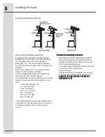
Page 8: ...The use of flexible metal round duct should only be used when no other duct fitting exists Limit use to short lengths and do not crush when making corners Ductwork and wiring locations Ductwork and wiring locations Ductwork and wiring locations Ductwork and wiring locations Ductwork and wiring locations t Determine the exact location of the vent hood t Locate the template packed with the literatur...

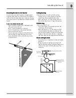
Page 9: ... the wall with wood screws and or fasteners Ceiling ducting Ceiling ducting Ceiling ducting Ceiling ducting Ceiling ducting If the duct will vent straight up to the ceiling t Use level to draw a line straight up from the centerline on the template to the ceiling t Measure at least 4 3 4 from the back wall to the circle center of an 8 hole on the ceiling W W W W Wall ducting all ducting all ducting...

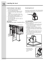
Page 10: ...100 lbs Mounting the hood 2 people are required to lift and position the hood onto the mounting screws Place the template on the wall along the horizon tal line make sure the template is leveled and centered with the centerline Mark upper screw holes locations in the wall IMPORTANT Check to be sure that hole locations are leveled and correctly centered by the vertical centerline Drive upper wood s...

Page 11: ...all or ceiling vent exit Air deflector installation Air deflector installation Air deflector installation Air deflector installation Air deflector installation Recir Recir Recir Recir Recirculating accessories culating accessories culating accessories culating accessories culating accessories t Assemble the air deflector with the duct cover bracket with 4 assembly screws provided as shown t Measur...

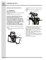
Page 12: ...n death or electrical shock Remove junction box cover and knockout on the top left side Installing the hood If not already done install 1 2 conduit connector in j box NOTE This connector is not included with vent hood Run black live white neutral and green earth wires 14 AWG according to the National Electrical Code or CSA Standards and local codes and ordinances in 1 2 conduit from power supply t...

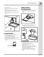
Page 13: ... t Position the top of the duct over the duct mounting bracket If a telescopic duct cover is used grab the upper part of the telescopic duct cover pull it and place it in the duct cover mounting bracket t Secure the top of the duct with 2 assembly screws provided t Secure the bottom of the duct with 2 assembly screws provided Instal the grease filter and turn power on at service panel Check operat...

Page 14: ...ures 1 1 1 1 1 Blower and light controls 2 2 2 2 2 Lamp housings 3 3 3 3 3 Grease filter Handle 4 4 4 4 4 Grease filter 5 5 5 5 5 Canopy 6 6 6 6 6 Duct covers 7 7 7 7 7 Louver holes Only for Recirculating version Features ...

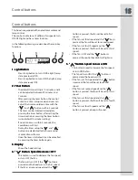
Page 15: ...ribed the main key functions 1 Light Button 1 Light Button 1 Light Button 1 Light Button 1 Light Button t Press lamp button to turn ON the light Lamp state previously OFF t Press lamp button to turn OFF the light Lamp state previously ON 2 Timer Button 2 Timer Button 2 Timer Button 2 Timer Button 2 Timer Button t The default timer setting is 10 minutes and it can be adjusted between 20 minutes and...

Page 16: ... on display the charcoal filters installed are required to be replaced or reactivated t To reset the charcoal filter saturation indication the user must press the button for 5 seconds after this time the icon Char Char Char Char Charcoal filter coal filter coal filter coal filter coal filter is not displayed and the hood has the normal display operation Audible signal activation and deactivation A...

Page 17: ...lish air currents upward through the hood Thus when heat smoke moisture grease and cooking odors are produced they will be carried outside instead of drifting into other rooms t Use the low speeds for normal use and the higher speeds for strong odors or fumes t Drafts across the range or cooktop will cause the escape of heat smoke moisture grease and cooking odors from the hood Such drafts should ...

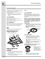
Page 18: ...re replacing it Care and cleaning Lights Before replacing the lamps switch power off at service panel and lock service panel disconnecting means to prevent power from being switched on accidentally Replace Lights Remove the inner lamp lens cover by inserting a slots and gently prying it free NOTE Do not remove the outer trim ring lamp assembly Grasp the bulb and pull it straight out from the lamp ...

Page 19: ...se the mildest cleaner that will do the job Use clean soft cloths sponges or paper towels grain Wipe area dry to avoid water marks After cleaning place all parts in their proper positions before using The cleaners recommended below indicate a type and do not constitute an endorsement Use all products according to package directions Hood Surface Painted Surfaces For general care wipe the outside of...

Page 20: ...SCLAIMER OF IMPLIED WARRANTIES LIMITATION OF REMEDIES CUSTOMER S SOLE AND EXCLUSIVE REMEDY UNDER THIS LIMITED WARRANTY SHALL BE PRODUCT REPAIR OR REPLACEMENT AS PROVIDED HEREIN CLAIMS BASED ON IMPLIED WARRANTIES INCLUDING WARRANTIES OF MERCHANTABILITY OR FITNESS FOR A PARTICULAR PURPOSE ARE LIMITED TO ONE YEAR OR THE SHORTEST PERIOD ALLOWED BY LAW BUT NOT LESS THAN ONE YEAR ELECTROLUX SHALL NOT BE...

Page 21: ...LI287D ...

Reviews: