background image

8

OPERATION

FIG. 7

OIL 
FILLER
PLUG

OIL 
LEVEL

TO START ENGINE (See Fig. 8)

CAUTION:  Keep drive control bar in 
“DISENGAGED” position when start-
 ing en gine.

When starting engine for the fi rst time or if engine has run 
out  of fuel, it will take extra pulls of the recoil starter to 
move fuel from the tank to the engine.
•      Make sure spark plug wire is prop er ly connected.
•      Move shift lever indicator to “N” (neutral) position.
•      Place throttle control in “FAST” position.
•     Move choke control to full “CHOKE” position. Grasp 

recoil starter handle with one hand and grasp tiller 
handle with other hand.  Pull rope out slowly until en-
gine reaches start of com pres sion cycle (rope will pull 
slightly harder at this point).

•     Pull recoil starter handle quickly.  Do not let starter 

handle snap back against starter.  Repeat if neces-
sary.

•      If engine fi res but does not start, move choke control 

to half choke position. Pull recoil starter handle until 
engine starts.

•     When engine starts, slowly move choke control to 

“RUN” position as engine warms up.

NOTE:  

A warm engine requires less choking to start.  

•      Move throttle control to desired running position.
•     Allow engine to warm up for a few minutes before 

engaging tines.

NOTE:

  If at a high altitude (above 3000 feet) or in cold 

temperatures (below 32°F), the carburetor fuel mix ture may 
need to be adjusted for best engine per for mance.  See “TO 
ADJUST CARBURETOR” in the Service and Ad just ments 
section of this manual.

NOTE:

  If en 

gine does not start, see trou 

ble shoot ing 

points.

BEFORE STARTING ENGINE

IMPORTANT

:   BE VERY CAREFUL NOT TO ALLOW DIRT 

TO ENTER THE ENGINE WHEN CHECKING OR ADDING 
OIL OR FUEL.  USE CLEAN OIL AND FUEL AND STORE IN 
AP PROVED, CLEAN, COVERED CONTAINERS.  USE CLEAN 
FILL FUNNELS.

FILL ENGINE WITH OIL (See Fig. 7)

•      With engine level, remove engine oil fi ller plug.
•      Fill engine with oil to point of overfl owing.  For ap prox-

i mate ca pac i ty see “PRODUCT SPEC I FI CA TIONS” on 
page 3 of this manual.

•      Tilt tiller back on its wheels and then re-level.
•     With engine level, refi ll to point of overfl owing if nec-

 es sary.  Re place oil fi ller plug.

•      For cold weather operation you should change oil for 

easier starting (See  “OIL VISCOSITY CHART” in the 
Maintenance section of this manual).

•      To change engine oil, see the Maintenance section of 

this manual.

ADD GASOLINE 

•     Fill fuel tank to bottom of fi ller neck. Do not overfi ll.  

Use fresh, clean, regular un lead ed gasoline with a 
minimum of 87 octane.  (Use of  leaded gasoline will 
increase carbon and lead oxide deposits and reduce 
valve life).  Do not mix oil with gasoline.  Purchase fuel 
in quan ti ties that can be used within 30 days to assure 
fuel freshness.

CAUTION:  Fill to within 1/2 inch of top 
of fuel tank to prevent spills and to allow 
for fuel expansion.  If gasoline is ac-
 ci den tal ly spilled, move machine away 
from area of spill.  Avoid creating any 
source of ignition until gasoline vapors 
have disappeared.  

Wipe off any spilled oil or fuel.  Do not 
store, spill or use gasoline near an 
open fl ame.

IMPORTANT:

  WHEN OPERATING IN TEMPERATURES 

BELOW32°F(0°C), USE FRESH, CLEAN WINTER GRADE 
GAS O LINE TO HELP INSURE GOOD COLD WEATHER 
START ING.

CAUTION:  Alcohol blended fuels (called 
gas o hol or using ethanol or methanol) can at-
tract moisture which leads to sep a ra tion and 
for ma tion of acids during storage.  Acidic gas 
can damage the fuel system of an engine while 
in storage.  To avoid engine problems, the fuel 
system should be emptied before stor age of 
30 days or longer.  Drain the gas tank, start 
the engine and let it run until the fuel lines 
and carburetor are empty.  Use fresh fuel next 
sea son.  See Storage In struc tions for additional 
information.  Never use engine or carburetor 
cleaner products in the fuel tank or permanent 
damage may occur.

Summary of Contents for Rally FN620K

Page 1: ...s Storage Troubleshooting Repair Parts OWNER S MANUAL 184873 11 27 02 TR PRINTED IN U S A MODEL NO FN620K 3 5 HP 17 Inch Tiller 00137 For Parts and Service contact our authorized distributor call 1 800 849 1297 For Technical Assistance call 1 800 829 5886 ...

Page 2: ...to stop the unit and disengage the controls quickly Never allow children to operate the equipment Never allow adults to operate the equipment without proper instruction Keep the area of operation clear of all persons par ticularly small children and pets PREPARATION Thoroughly inspect the area where the equipment is to be used and remove all foreign objects Disengage all clutches and shift into ne...

Page 3: ... SPARK ARRESTER IS USED IT SHOULD BE MAINTAINED IN EFFECTIVE WORKING ORDER BY THE OPERATOR IN THE STATE OF CALIFORNIA A SPARK ARRESTER IS REQUIRED BY LAW SECTION 4442 OF THE CALIFORNIA PUBLIC RESOURCES CODE OTHER STATES MAY HAVE SIMILAR LAWS FEDERAL LAWS APPLY ON FEDERAL LANDS SEE YOUR AUTHORIZED SERVICE CENTER FOR SPARK ARRESTER PRODUCT SPECIFICATIONS GASOLINE CAPACITY 2 Quarts 1 89L Unleaded Reg...

Page 4: ...n of your tiller all parts and hardware you assemble must be tightened securely Use the correct tools as necessary to insure proper tightness TOOLS REQUIRED FOR ASSEMBLY A socket wrench set will make assembly easier Standard wrench sizes are listed 1 Utility knife 1 Pair of pliers 1 Screwdriver 2 1 2 wrenches OPERATOR S POSITION RIGHT FRONT LEFT FIGURE 1 6 Lock Washers 5 16 6 Hex Nuts 5 16 18 2 He...

Page 5: ...ur tilling conditions See TINE ARRANGEMENT in the Service and Adjustments section of this manual TINE OPERATION Check tine operation before first use See TINE OP ERATION CHECK in the Service and Adjustments section of this manual UNPACK CARTON INSTALL HANDLE See Fig 2 CAUTION Be careful of exposed staples when handling or disposing of cartoning material IMPORTANT WHEN UNPACKING AND ASSEMBLING TILL...

Page 6: ...THROTTLE CONTROL These symbols may appear on your Tiller or in literature supplied with the product Learn and understand their meaning FIG 4 MEETS ANSI SAFETY REQUIREMENTS Our tillers conform to the safety standards of the American National Standards Institute FORWARD TINE CONTROL Engages tines in forward direction THROTTLE CONTROL Controls engine speed CHOKE CONTROL Used when starting a cold engi...

Page 7: ...ent ENGINE Move throttle control to STOP position Never use choke to stop engine HOW TO USE YOUR TILLER Know how to operate all controls before adding fuel and oil or attempting to start engine TINE OPERATION See Fig 5 Squeeze tine control to handle TILLING The speed and depth of tilling is regulated by the position of the depth stake and wheel height The depth stake should always be below the whe...

Page 8: ... engine level remove engine oil filler plug Fill engine with oil to point of overflowing For approx imate capacity see PRODUCT SPECIFICATIONS on page 3 of this manual Tilt tiller back on its wheels and then re level With engine level refill to point of overflowing if nec essary Replace oil filler plug For cold weather operation you should change oil for easier starting See OIL VISCOSITY CHART in t...

Page 9: ...andlingyourtiller startactualfielduse with throttle in slow position mid way between FAST and IDLE To help tiller move forward lift up the handles slightly thus lifting depth stake out of ground To slow down the tiller press down on handles If you are straining or tiller is shaking the wheels and depth stake are not set properly in the soil being tilled The proper setting of the wheels and depth s...

Page 10: ...un better and last longer BEFORE EACH USE Check engine oil level Check tine operation Check for loose fasteners LUBRICATION Keep unit well lubricated See LUBRICATION CHART MAINTENANCE SCHEDULE FILL IN DATES AS YOU COMPLETE REGULAR SERVICE Check Engine Oil Level Change Engine Oil Oil Pivot Points Inspect Air Screen Inspect Spark Arrester Muffler Clean or Replace Air Cleaner Cartridge Clean Engine C...

Page 11: ... Select the oil s SAE viscosity grade according to your expected temperature NOTE Although multi viscosity oils 5W 30 10W 30 etc improve starting in cold weather these multi viscosity oils will result in increased oil consumption when used above 32 F 0 C Check your engine oil level more frequently to avoid possible engine damage from running low on oil Change the oil after every 25 hours of operat...

Page 12: ...ENANCE COOLING SYSTEM See Fig 14 Your engine is air cooled For proper engine performance and long life keep your engine clean Clean air screen frequently using a stiff bristled brush Remove blower housing and clean as necessary Keep cylinder fins free of dirt and chaff FIG 14 MUFFLER CYLINDER FINS BLOWER HOUSING AIR SCREEN CLEANING Do not clean your tiller when the engine and transmission are hot ...

Page 13: ...ARRANGEMENT Your outer tines can be assembled in several different ways to suit your tilling or cultivating needs CAUTION Tines are sharp Wear gloves or other protection when han dling tines NORMAL TILLING 17 PATH See Fig 16 Assemble holes A in tine hubs to holes B in tine shaft FIG 16 FIG 17 B A CLEVIS PIN INNER TINE OUTER TINE B A HAIRPIN CLIP MID WIDTH TILLING 15 PATH See Fig 17 Assemble holes ...

Page 14: ... handle while observing tines Tines should rotate forward If tines do not rotate place loop of idler spring in a higher link of chain and retest NOTE If ON positioncheckrequiredadjustment recheck OFF positionadjustmenttoinsuretinesdonotrotatewhen control is OFF up NOTE Additional tine arrangements can be attained by moving outer tines to opposite side of tiller which will point tines outward Alway...

Page 15: ...nd rests on idler pulley CHECK TINE OPERATION See TINE OPERATION CHECK in this section of manual REPLACE BELT GUARD ENGINE TO ADJUST CARBURETOR The carburetor has a high speed fixed jet and has been preset at the factory and adjustment should not be nec essary However minor adjustments may be required to compensate for differences in fuel temperature altitude or load If the carburetor does need ad...

Page 16: ... Inspect and replace belts if necessary See belt re placement instructions in the Service and Adjustments section of this manual Lubricate as shown in the Maintenance section of this manual Be sure that all nuts bolts and screws are securely fastened Inspect moving parts for damage breakage and wear Replace if necessary Touch up all rusted or chipped paint surfaces sand lightly before painting ENG...

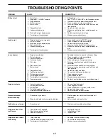
Page 17: ...r 6 Stale or dirty fuel 6 Drain fuel tank and refill with fresh gasoline 7 Water in fuel 7 Drain fuel tank and carburetor and refill tank with fresh gasoline 8 Clogged fuel tank 8 Remove fuel tank and clean 9 Spark plug wire loose 9 Connect and tighten spark plug wire 10 Dirty engine air screen 10 Clean engine air screen 11 Dirty clogged muffler 11 Clean replace muffler 12 Carburetor out of adjust...

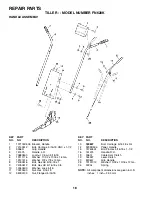
Page 18: ...6 18 x 1 9 74760512 Bolt Hex Hd 5 16 18 x 3 4 10 10040500 Washer Lock 5 16 11 73220500 Nut Hex 5 16 18 12 98000129 Nut Flanged 5 16 18 KEY PART NO NO DESCRIPTION KEY PART NO NO DESCRIPTION NOTE All component dimensions are given in U S inches 1 inch 25 4 mm 13 180847 Bolt Carriage 5 16 18 x 3 4 14 9209R505 Panel Handle 15 74760524 Bolt Fin Hex 5 16 18 x 1 1 2 16 151474 Handle R H 18 3067J Cable As...

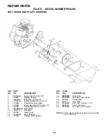
Page 19: ...Nut Hex Jam 5 16 18 KEY PART NO NO DESCRIPTION 1 23230506 Screw Set 5 16 18 x 3 8 2 130812 Sheave Engine 4 74610812 Bolt Hex 1 2 20 x 3 4 5 17490440 Bolt Thd Roller 1 4 20 X 2 1 2 6 174898 Shield Inner Guard Belt 7 170488 Screw Hex Wsh Slt 10 24 x 50 8 139155 Spacer Split 523 x 718 x 2 9 165768X505 Guard Belt 10 109227X Pad Idler 12 9180R V Belt Drive 13 12000028 Ring Retainer 14 151223 Sheave Tra...

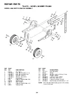
Page 20: ...H 9 9193R Stake Depth 10 9551R Rivet Drilled 13 317J Support Depth Stake L H 15 5388J Spring Stake KEY PART NO NO DESCRIPTION 16 121117X Bolt Shoulder 17 9186R Wheel 18 19131311 Washer 13 32 x 13 16 x 11 Ga 19 9190R Bracket Wheel 20 73680600 Locknut Crown 3 8 16 21 74760516 Bolt Hex 5 16 18 x 1 22 73800500 Locknut w insert 5 16 18 23 74780524 Bolt Fin Hex 5 16 18 UNC x 1 1 2 KEY PART NO NO DESCRIP...

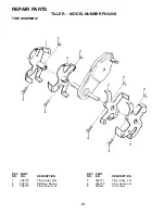
Page 21: ...PTION 1 165774 Tine Outer R H 2 4921H Retainer Spring 3 165772 Tine Inner R H 4 165771 Tine Inner L H 5 165773 Tine Outer L H 6 9194R Pin Clevis KEY PART NO NO DESCRIPTION REPAIR PARTS TILLER MODEL NUMBER FN620K TINE ASSEMBLY ...

Page 22: ...s from engine Manufac turer KEY PART NO NO DESCRIPTION 1 74760524 Bolt Hex 5 16 18 x 1 1 2 Gr 2 2 74780652 Bolt Hex Fin 3 8 16 x 3 1 4 3 19131311 Washer 13 32 x 13 16 x 11 5 73800600 Locknut Hex w washer 3 8 16 6 9056R505 Shield Tine 7 165835 Bracket Engine R H 8 165834 Bracket Engine L H 10 73970500 Nut Lock Hex Flange 11 74760544 Bolt Hex 5 16 18 x 2 3 4 12 151937 Transmission 14 9173R Spacer Sp...

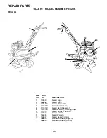
Page 23: ...ne Control 6 110614X Decal Hand Placement 8 120076X Decal Warning Rotating Tines 9 171803 Decal Briggs Stratton 10 171806 Decal 3 5 HP 11 162384 Decal Warning 12 165327 Decal Speed Control 184873 Manual Owner s English 184874 Manual Owner s French 1 2 11 10 REPAIR PARTS TILLER MODEL NUMBER FN620K DECALS 5 6 9 8 4 12 ...

Page 24: ...Warranty does not apply to any product which has been subjected to alteration misuse abuse improper assembly or installation delivery damage or to normal wear of the product 5 Exclusions Excluded from this Warranty are belts tines tine adapters normal wear normal adjustments stan dard hardware and normal maintenance 6 In the event you have a claim under this Warranty you must return the product to...

Reviews: