background image

Doc. No.:           

560001 EG

Page:31           

Ed.1" 08-2014

From ser. no.:

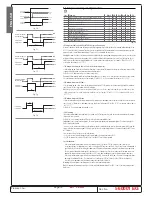
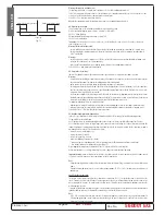
ON

OFF

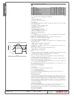
Amb.

Amb. F1

Amb. F1 - A0

Evap.

Evap. Fan

te

mperatura

Fig. 7.o

ENGLISH

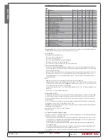
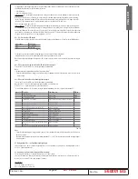
7.6 Fan management parameters

Code

Parameter

Models

UOM

Type

Min

Max

Def.

F0

Fan management

---F

fl ag

C

0

2

0

F1

Fan start temperature

---F

°C/°F

F

-50

200

5.0

F2

Fan OFF with compressor OFF

---F

fl ag

C

0

1

1

F3

Fans in defrost

---F

fl ag

C

0

1

1

Fd

Fan OFF after dripping

---F

min

F

0

15

1

F4

Condenser fan stop temperature 

MSYF

°C/°F

C

-50

200

40

F5

Condenser fan start diff erential

MSYF

°C/°F

C

0.1

20

5.0

Tab. 7.l

The ir33 series controllers manage the evaporator fans in the following modes:
• always ON;
•  ON only when the compressor is ON;
•  ON according to evaporator and room temperature.

F0: Fan management

The fans can be always on or managed by the “fan controller”, which controls them according to the temperature measured by the 
defrost and virtual control probes.
The evaporator fans can be stopped in the following situations:
•  when the compressor is OFF (see parameter F2);
•  during defrosts (see parameter F3);
•  during the dripping period (see parameter dd);
•  and for a further post-dripping period (see parameter Fd);
• in defrost they can be on or off  (see parameter F3).
The following values are allowed for this parameter:
F0=0 fans always ON;
F0=1 fans controlled according to the temperature diff erence between the virtual control probe and the evaporator temperature;
F0=2 fans controlled according to the evaporator temperature.

Warning:

 remember that if a dripping period is set (dd=0), the fans are stopped irrespective of the value of F0.

Default: F0=0 => fans always ON, not managed by the “fan controller”.

F1: Fan start temperature (parameter valid only if F0 =1 or 2)

When F0=1, parameter F1 indicates the minimum diff erence between room temperature and evaporator temperature for the fans 
to be started. Therefore, when:
•  evaporator temperature < (virtual probe – F1-A0), the fans are ON;
•  evaporator temperature > (virtual probe – F1), the fans are OFF.
When stopped, the fans can start again when the diff erence between the two probes is equal to F1+A0, where A0 is the “fan 
controller” diff erential (see Figure 7.o).
When F0=2, parameter F1 indicates the absolute temperature for starting the fans, that is:
•  evaporator temperature < (F1-A0), the fans are ON;
•  evaporator temperature > (F1), the fans are OFF.

Notes:

•  if there are two evaporators and therefore two evaporator probes, control will be performed using the maximum value read by 

the two probes, to ensure that the fans are started when both evaporators reach the set temperature.

•  in the event of errors on the control probes, the fans are always on.
Default: F1=5 =>(if F0=1 or 2), the fans remain ON while the evaporator is 5 degrees colder than the room temperature.

F2: Fans OFF with compressor OFF (according to the value of F0)

Used to decide whether the fans must operate according to the rules set for parameter F0 (with the exception of the defrost cycle, 
parameters F3, dd and Fd are displayed) or when the compressor is active.
•  F2=0 => the fans are always ON (F0=0) or when requested by the fan controller (F0=1,2), even when the compressor is OFF;
•  F2=1 => the fans are OFF when the compressor is OFF.

Note: 

if control with two compressor steps is selected (with or without rotation, H1 or H5= 12 or 13) and parameter F2 =1, the 

fans are off  when both the compressors are off .
Default: F2=1 => fans OFF with compressor OFF.

F3: Fans in defrost

This is used to decide whether the fans should operate or not during the defrosts.
F3=0 => the fans operate during defrosts;
F3=1 => the fans do not operate during defrosts.
Remember that during the dripping time and post-dripping time, if specifi ed, the fans are always OFF. Default: F3=1 => 
evaporator fans OFF during the defrost.

Fd: Fans OFF for post-dripping

The fans, after defrosting, can be stopped for a further period beyond dd (in minutes), defi ned by the value of Fd. This is useful 
to allow the evaporator to return to its operating temperature after defrosting, thus avoiding forcing “hot” air into the refrigerated 
environment. In the event of management by fan controller, the time Fd does not need to be set, as the controller starts the fans 
again when the evaporator reaches its operating temperature. If the “fan controller” is active (F0=0), when assigning to Fd a value 
other than zero, the fans remain OFF for a time equal to the value of Fd, irrespective of the evaporator temperature. Default: Fd=1 
=> 1 minute stop for post-dripping.

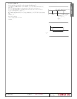
F4: Condenser fan stop temperature

This is used to select the temperature at which the condenser fans should be switched OFF. If setting the auxiliary relay as the 
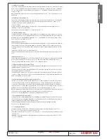
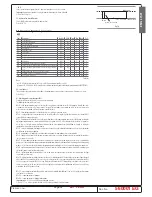
condenser fan output (see parameter H1), this will enable adjustments according to the diagram in Figure 7.p:
When the compressor is fi rst started, the fans are switched ON at F4 + 0.2 degrees to compensate for rapid temperature increases 
that are not easy for the probe to follow.
After this, control is performed normally, i.e.: 
•  on: F4 + F5

Summary of Contents for Premium

Page 1: ... Management controller Premium Standard Standard Model Model for Ecostore Premium CONTENTS Page Description 2 Buttons 3 Icons 4 Programming 5 to 7 Parameters view 8 to 9 Service Temperature alarms 10 Defrost algorithm 11 to 14 Spare part code of controller 15 to 40 Parameter descriptions ...

Page 2: ...s 1 2 3 4 5 6 7 PREMIUM 2 3 8 5 6 7 PREMIUM Description 1 ON OFF 2 History button 3 Programming confirmation button 4 Light button 5 Temperatura Programming button 6 Temperature decrease Turbo cooling button 7 Temperature increase Manual defrost button 8 Umidity button 3 6 1 7 5 3 6 1 4 5 Standard Control ...

Page 3: ...ernal digital input alarm Flashes in the event of alarms during normal operation e g high low temperature or in the event of alarms from an immediate or delayed external digital input Delayedexternalalarm beforethetime A7 elapses No alarm present Alarmsinnorm operation e g High lowtemperature orimmediateordelayedalarm fromexternaldigitalinput CLOCK Onincaseofconsultationhistorytemperature History ...

Page 4: ...le pressing the SET button will have no effect 4 it is possible to continue consulting the parameters or return to the categories menu with the PRG button 5 press SET to display the value associated with the parameter 6 increase or decrease the value respectively with the buttons and 7 press SET to temporarily save the new value and return to the display of the parameter Repeat the procedure from ...

Page 5: ...2 0 0 2 1 e b o r p n o i t a r b i l a C C F 10 9 c2 Calibrazione sonda 2 0 0 2 0 0 2 2 e b o r p n o i t a r b i l a C C F 10 10 c3 Calibrazione sonda 3 0 0 2 0 0 2 3 e b o r p n o i t a r b i l a C C F 10 11 St 2 r 1 r t n i o p t e S t n i o p t e S C F 12 rd Delta Regolatore 0 2 1 0 a t l e d l o r t n o C C F 13 r1 Set minimo ammesso 2 r 0 5 d e w o l l a t n i o p t e s m u m i n i M C F 14...

Page 6: ... attivato NUM_COMP_ON number of hours the compressor is on after which defrost must start 0 12 Hours 40 dF1 Numero di aperture porta dopo il quale il parametro DFO deve decrementare number of door openings after which dF0 must be decreased 0 500 Units 41 dF2 Minuti da sottrarre al parametro DF0 per anticipare lo sbrinamento minutes to be subtracted to dF0 in order to anticipate defrost 0 240 Min 4...

Page 7: ... e r l e d o t n e m a n o i z n u F 4 1 e v l a v o r t c e l e w o l F 4 1 a l o v l a v o r t t e l e o s s u l F 5 1 e c n a t s i s e r e m a r F 5 1 e c i n o c a z n e t s i s e R 8 t h g i l r o o d s s a l G 8 o r t e v a t r o p e c u L 2 e c n a t s i s e r e p i p n i a r D 2 a s n e d n o c o c i r a c s i d a z n e t s i s e R 75 H2 g a l F 6 0 6 N 1 Y F F O N O e l b a n E 6 N 1 Y F...

Page 8: ...ed Clean alarm when the condenser is very dirty on the display will appear the label CLn this alarm dosen t stop the cycle but only advises the customer to clean the condenser The CLn alarm appears only after 90 days to work of compressor and when the temperature of the condenser and ambient is over to delta of the parameter ACS The alarm disapears when the temperature decrease from parameter ACd ...

Page 9: ...ed In case of activation of continuous cycle by pressing the temperature decrease button for more than 5 seconds the display will show the message ccb at the same time as the temperature the message tc will appear meaning that turbo cooling has been activated The cycle will end for time by parameter CC or for temperature by parameter AL or by pressing the button again The humidity value is activat...

Page 10: ...NALLING HI LO TEMPERATURE ALARM TEMPERATURE ALARM SER SEr The icon light up and audible alarm sound when the compartement temperature exceeds the set maximun value The alarm ceases when the temperature returns to Set point A Parameter AL and AH determine the threshold of alarm of hight or lower temperature Another parameter as Ad determine the delay of alarm When the temperature return to set poin...

Page 11: ...erence to the total number of openings of the door Every time the programmed defrost is done the total on time hours of compressor and the number of door openings will be reset Proper parameters will be employed in order to manage this algorithm In order to do this consider flux diagram of Figure 3 4 For instance t_on_cmpr is the variable counting on time hours of compressor starting from last def...

Page 12: ...329 used on Mass and Gab glass door freezer and refrige rated 4 relay 16A 8A 8A 8A Factory code 646R11101 SPC 093434 used on Mass dual temp MASTER freezer and refrige rated 4 relay 16A 8A 8A 8A Factory code 646R11301 SPC 093438 used on Mass dual temp SLAVE freezer and refrigera ted 4 relay 16A 8A 8A 8A Factory code 646R10602 SPC 093437 used on Premium all and as Master on dual tempera ture 4 relay...

Page 13: ...e 646R11401 SPC 093439 used on Premium as Slave on dual temperature 4 relay 16A 8A 8A 8A Factory code 648R05000 SPC 093389 used on Premium dual doors and Super premium Factory code 648R05500 SPC 093388 used on Premium one doors and half doors Power Termoregulator ...

Page 14: ...Doc No 560001 EG Page 14 Ed 1 08 2014 From ser no Factory code 646R11500 SPC 0TH303 used on all Cabinets and couters all range asia sb line with power supply to 12V ...

Page 15: ...rature displayed and not the temperature used for the control functions Important the control temperature actually measured differs from the value displayed and therefore the outputs may not be activated with reference to the latter temperature value iftheprobedisplayedisaproductprobe withtemperaturevalueshigherthanthesetpoint theprobedisplayratealgorithmwill be faster for decreases in the tempera...

Page 16: ...are always set to the tenth of a degree 6 0 the readings are displayed to the tenth of a degree between 20 and 20 C 6 1 all the readings are displayed without the tenths of a degree Default 6 0 decimal point displayed tI Probe displayed on instrument For selecting the probe to be displayed by the instrument tI 1 virtual probe tI 2 probe 1 tI 3 probe 2 tI 4 probe 3 tI 5 probe 4 tI 6 probe 5 tI 7 se...

Page 17: ...pressing SET shows the value of the corresponding probe already corrected with the offset while pressing SET a second time displays the abbreviated code Default C1 C2 C3 C4 C5 0 no offset 7 2Temperature control parameters Code Parameter Model UOM Type Min Max Def St Temperature set point MSYF C F F r1 r2 0 0 rd Control delta SYF C F F 0 1 20 2 0 rn Dead band SYF C F C 0 0 60 4 0 rr Reverse differe...

Page 18: ... A5 A9 Note with r3 1 and r3 2 the defrosts are always disabled A digital input set for direct reverse cycle control with parameter r3 has priority over the operating mode The figure to the side shows reverse control with two compressor steps Default r3 0 Direct thermostat operation with defrost control r4 Automatic variation of the set point in night time operation This parameter is part of the g...

Page 19: ...ssor to remain OFF The compressor is not started again until the minimum time selected c2 has elapsed from when it last stopped Note this parameter is useful to ensure the balancing of the pressure after the compressor stops for systems with hermetic and capillary compressors The second compressor step for the aux 1 or 2 output H1 or H5 12 13 is associated with the timers c0 c1 c2 c3 c3 Minimum co...

Page 20: ... down is disabled Default c7 0 pump down disabled c8 Compressor start delay after opening of PD valve This parameter determines after how many seconds from the opening of the pump down valve the compressor starts It is useful to avoid activating the LP alarm unnecessarily The low pressure alarm LP with valve open and compressor ON is activated by the opening of the pressure switch This alarm stops...

Page 21: ...vates the defrost output and then reactivates it if the related evaporator probes measure a temperature below dt1 and dt2 1 C This occurs for the entire duration of the defrost set using the parameter dP Note model S does not have a defrost relay and consequently the defrost can only be performed by stopping the compressor and selecting end of defrost by time or temperature If the alarms Ed1 and E...

Page 22: ...o If the frequency of the power failure were in an extreme case greater than the defrost frequency e g a power failure every hour against a defrost every 10 hours the controller would never perform a defrost In a situation of this type it is preferable to enable defrost on start up above all if the defrost is controlled by temperature probe on the evaporator therefore avoiding unnecessary defrosts...

Page 23: ... start of the defrost Compressor protection times c1 minimum time between 2 successive starts c2 minimum OFF time c3 minimum operating time d9 0 the protection times are respected d9 1 the protection times are not respected Therefore defrost has higher priority and the compressor times are ignored In the hot gas defrost this is useful to avoid delaying the start of the defrost if the compressor ha...

Page 24: ...gh condenser temperature alarm SYF C F C 0 0 200 70 0 AE High condenser temperature alarm differential SYF C F C 0 1 20 5 0 Acd High condenser temperature alarm delay SYF min C 0 250 0 AF Light sensor OFF time SYF sec C 0 250 0 ALF Antifreeze alarm threshold MSYF C F C 50 200 5 0 AdF Antifreeze alarm delay MSYF min C 0 15 1 Tab 7 g Note par A9referstotheinstrumentswith3digitalinputs ir33DIN powerc...

Page 25: ...ture alarm The following conditions generate the temperature alarms high temperature alarm the temperature measured by the virtual control probe is above the threshold set for parameter AH low temperature alarm the temperature measured by the virtual control probe is below the threshold set for parameter AL Default Ad 120 120 minute delay for the temperature alarms A4 Multifunction digital input c...

Page 26: ...ting a different value for d5 on each unit will avoid simultaneous defrosts Note if more than one digital input is configured to enable the defrost the defrost will be disabled when at least one of the inputs is closed A4 5 Door switch with compressor and fan stop Setting A4 5 manages the cold room door switch The behaviour of the door switch depends on whether the door is opened with the light OF...

Page 27: ... the value used when the curtain is open Contact closed curtain lowered If one of the auxiliary outputs is used to manage the light lowering the curtain automatically switches the light off while raising it switches the light on Note if more than one digital input is configured as a curtain switch the curtain open status occurs when at least one of the inputs is open A4 8 Low pressure switch input...

Page 28: ... algorithm depends on the parameter Ado 2 if more than one digital input is configured as the door switch the door open status will be considered when at least one of the inputs is open A4 14 Door switch with fans only off and light not managed Same as for A4 9 with the difference that the light output is not modified Note for A4 5 13 or 14 the Ado door management algorithm is used in both cases D...

Page 29: ... manually In the event of a condenser probe fault the alarm and pre alarm are activated Note if control with two compressor steps is selected with or without rotation H1 12 or 13 the high condenser temperature alarm acts on both steps Important 1 if no condenser probe is selected the condensing temperature alarm and pre alarm are disabled 2 the condenser fans can be controlled in on off mode for t...

Page 30: ...robe has been set as an antifreeze probe A2 A3 A4 A5 4 and is delayed by the time set for parameter AdF The antifreeze alarm stops the compressor and activates the alarm relay if H1 or H5 0 1 and has manual reset The antifreeze alarm stops the compressor stops cooling operation and activates the alarm relay if H1 0 1 or H5 0 1 The alarm is reset manually or from the supervisor Note if control with...

Page 31: ...ator probes control will be performed using the maximum value read by the two probes to ensure that the fans are started when both evaporators reach the set temperature in the event of errors on the control probes the fans are always on Default F1 5 if F0 1 or 2 the fans remain ON while the evaporator is 5 degrees colder than the room temperature F2 Fans OFF with compressor OFF according to the va...

Page 32: ...or connected can be switched ON OFF using the AUX button Switching the actuator ON OFF is signalled by the icon on the display H1 3 lightoutput thelightontheunitcanbeswitchedon offwhenthedoorisopened pressingtheLIGHTbutton enablingthe digital input switch door or the curtain switch digital input see parameter A4 A A6 if the door switch is enabled see parameter A4 In this case the light is switched...

Page 33: ...ock keypad Using the corresponding bits the functions relating to the individual buttons on the keypad can be enabled disabled according to the following relationships Total value of parameter H6 to calculate the value to be assigned to parameter H6 simply sum the values assigned to the functions that should be disabled For ir33 ir33power and ir33DIN seeTable 7 q for powercompact powercompact smal...

Page 34: ...H5 2 3 8 9 deactivated while the control temperature virtual probe is less than St Hdh when the instrument is first powered up the HI IA dA CHt EE EF rE alarms are reset During the aforementioned alarms the aux 1 or 2 output configured as above is deactivated The function is active if the light or aux functions are set to be deactivated when off H1 or H5 8 9 even when switching the controller on D...

Page 35: ...start in pump down cht No off off automatic manual high condenser temperature pre alarm CHT flashing on on manual high condenser temperature alarm dor flashing on on automatic door open too long alarm Etc flashing off off automatic manual real time clock fault EE flashing off off automatic E2prom error unit parameters EF flashing off off automatic E2prom error operating parameters HA flashing off ...

Page 36: ...ged dor unchanged unchanged unchanged unchanged unchanged unchanged Etc unchanged unchanged unchanged unchanged unchanged unchanged EE off off notperformed off off notperformed EF off off notperformed off off notperformed HA unchanged unchanged unchanged unchanged unchanged unchanged HF unchanged unchanged unchanged unchanged unchanged unchanged n1 n6 unchanged unchanged unchanged unchanged unchan...

Page 37: ...Doc No 560001 EG Page 37 Ed 1 08 2014 From ser no E N G L I S H NOTE ...

Page 38: ......

Reviews: