4
Control Panel
A
B C D
E
min
MAX
Operation
Insert the plug into the wall socket. Turn the
thermostat knob (E), clockwise, beyond the
Ç
■
È
(STOP) position.The pilot light (D) will light up,
indicating that the appliance is powered. The
warning light (C) will light up, indicating that the
temperature inside the appliance is too high.
To stop operation, simply turn the thermostat knob to
position
Ç
■
È
.
Temperature regulation
The temperature is automatically regulated and can
be increased to achieve a higher temperature
(warmer) by rotating the thermostat knob towards
minimum or reduced (colder) by rotating the knob
towards maximum. However, the exact setting
should be chosen keeping in mina that the
temperature inside the refrigerator depends on:
¥ room temperature;
¥ how often the door is opened;
¥ the quantity of food stored;
¥ location of appliance.
A medium setting is generally the most suitable.
A.
Normal/Super push button
B.
Super control light
C.
Warning light
D.
Pilot light
E.
Thermostat knob
Quick-freezing
For quick-freezing, push the button (A). The super
control light (B) will then light up.
Warning light (C)
The temperature alarm light turns on automatically
whenever the temperature within the freezer rises
above a certain value which might endanger
satisfactory long-term conservation.
It is perfectly normal for the temperature alarm light
to remain lit up for a short time after the freezer is
initially turned on. It will remain lit up until the
optimum temperature for the conservation of frozen
food is attained.
Freezing fresh food
The 4-star compartment is suitable for long term
storage of commercially frozen food and for freezing
fresh food.
To freeze fresh foods allow it to run on the fast
freeze setting for at least 24 hours before loading
food.
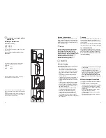
Place the food to be frozen in the compartments as
shown in figure.
D670
9 Kg
7 Kg
9
D726
B
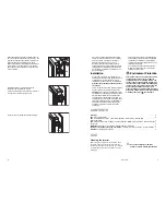
Apply covers (B) on joint cover lugs and into hinge
holes.
D724
Apply the sealing strip pushing it between the
refrigerator and the adjacent cabinet.
Place guide (A) on the inside part of the furniture
door, up and down as shown in the figure and mark
the position of external holes. After having drilled
holes, fix the guide with the screws supplied.
20 mm
A
50mm
PR166
Separate parts A, B, C, D as shown in the figure
PR266
A
B
C
D
PR33
C
A
Fix cover (C) on guide (A) until it clips into place.

