14
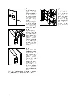
Fig. 8
Position the runners
(E) at the top and
bottom of the inside
of the kitchen unit
as shown in Fig. 8
and mark the posi-
tion of the external
holes.
After preparing the
holes, screw the
runners to the kitch-
en unit door using
3.5x16 mm screws.
Fig. 9
Open both the ap-
pliance door and
that of the kitchen
unit to approx. 90
°
.
P l a c e t h e l i t t l e
p l a t e s o v e r t h e
runners. Hold the
doors of the appli-
ance and the unit
together and mark
the holes.
Fig. 10
Remove the little
plates and make
the holes with a di-
am. of 2 mm. Re-
p l a c e t h e l i t t l e
p l a t e s o v e r t h e
runners and screw
in the screws pro-
vided (3.5x16 mm).
For the alignment of
t h e k i t c h e n u n i t
door, if necessary,
use the clearance
size of the slotted
holes.
At the end of the procedure, check that the doors of
the appliance and the kitchen unit open properly.
D285
20mm
E
8mm
PR34
PR35
Fig. 11
In case of side fix-
ing of the appli-
ance, it will be suf-
ficient to loosen
the screws fixing
t h e b r a c k e t s ( F )
a n d t o p o s i t i o n
them as shown in
F i g . 1 1 . F i n a l l y,
mount the cover
(G).
D317
G
H
G


