Electrolux EHTA060 Installation And Operating Manual Download Page 27

27

• Switch off the dishwasher by pressing the On/Off button.

• Switch off at the mains.
• Close the water supply tap.
• Replace the filter and the overflow.

K.2.1

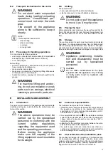
Cleaning the nozzle jets

• Remove the upper and lower wash arms “F“ and rinse arms

“I“, unscrewing the ring nut “H“.

• Carefully clean the washing and rinse jets and clean

everything with hot water and neutral detergent/detersive,
if necessary using a soft brush or sponge.
Do not use sharp implements to clean the nozzle holes,
which could otherwise be damaged.

• Replace the upper and lower wash arms and rinse arms.

K.3

Maintenance

The inspection and maintenance intervals depend on the
actual machine operating conditions (total wash hours) and
ambient conditions (presence of dust, damp, etc), therefore
precise time intervals cannot be given. In any case, careful and
periodical machine maintenance is advisable in order to
minimise service interruptions.

It is advisable to:
• Descale the boiler, inner surfaces of the tank and the

machine's pipes once or twice a year (call the Customer
Care Service).

• Every month descale the wash and rinse jets with vinegar or

scale remover.

• The internal tube of the peristaltic rinse aid and detergent

dispenser must undergo periodical maintenance (once or
twice a year).

NOTE!
It is also advisable to sign a preventive and
scheduled maintenance contract with the Cus-
tomer Care Service

K.3.1

Repair and extraordinary maintenance

Repair and extraordinary Maintenance have to be carried out
by specialised authorised personnel. The manufacturer
declines any liability for any failure or damage caused by the
intervention of an unauthorized technician by the Manufacturer
and the original manufacturer warranty will be invalidated.

K.3.2

Parts and accessories

Use only original accessories and/or spare parts. Failure to
use original accessories and/or spare parts will invalidate the
original manufacturer warranty and may render the machine
not compliant with the safety standard.

K.3.3

Prolonged period of inactivity

If the dishwasher is not to be used for a long time, proceed as
follows:

• Close the water supply tap.
• Completely drain the tank.
• Remove and carefully clean the filters.
• Completely drain the incorporated dispenser hoses, remov-

ing them from the containers. Repeat the procedure
described in the paragraph H.1

Manual activation

at least 3

times.

• Completely drain the boiler (see paragraph K.4

Boiler

drainage

).

• Spread a thin film of Vaseline oil over all the stain-less steel

surfaces.

K.4

Boiler drainage

If the appliance is not to be used for a long time, empty out the
boiler to prevent any malfunction and/or mildew and unpleas-
ant odours.

• Close the hood.
• Press simultaneously and hold “Drain/Self Cleaning“ button

and button “L“ (refer to F.1

Control panel description

).

• A buzzer indicates the rinse pump activation and the display

shows three blinking lines.

• Three beeps indicate the end of the cycle.

K.5

Preventive maintenance

Preventive maintenance reduces downtime and maximizes
machines efficiency. Customer Care Service can provide
advice on the best maintenance plan to be purchased based
on the intensity of use and the age of the equipment.
The preventive maintenance call may be activated (see
service manuals). Upon reaching the set number of cycles (e.

g. 20000),

appears on the display.

This message advises calling a Customer Care service for a
general check-up of the state of the machine.

3

B

2

1

2

1

3

4

A

3

1

C

H

F

I

Summary of Contents for EHTA060

Page 1: ...Hood Dishwasher EHTA060 ZHT060 VHT060 EN Installation and operating manual Original instructions 59566V600 2020 06 ...

Page 2: ...2 Installation diagram Manual hood type ...

Page 3: ...3 Installation diagram Automatic hood type ...

Page 4: ...let pipe 3 4 G D Drain pipe internal 40 mm ʌ 20 mm ʌ Only for model with free fall drainage Only for model with drain pump EI Electrical Inlet EQ Equipotential screw XD Inlet pipe for detergents XR Inlet pipe for rinse aid XI Inlet pipe for delime ...

Page 5: ...hine is used so that it is always at hand for consultation in case of doubts or whenever required If after reading this manual there are still doubts regarding machine use do not hesitate to contact the Manufacturer or the au thorised Service Centre to receive prompt and precise assistance for better operation and maximum efficiency of the machine During all stages of machine use always respect th...

Page 6: ...tioning 14 E 6 Extraction hood 14 E 7 Disposal of packing 15 E 8 Plumbing connections 15 E 9 Plumbing circuits 15 E 10 Electrical connections 15 E 10 1 Connections provided for energy control 16 E 11 Safety devices 16 E 12 HACCP arrangement 16 F CONTROL PANEL 17 F 1 Control panel description 17 F 2 Basic Controls 17 G COMMISSIONING 18 G 1 Preliminary checks adjustments and operational tests 18 G 2...

Page 7: ...ts and accessories 27 K 3 3 Prolonged period of inactivity 27 K 4 Boiler drainage 27 K 5 Preventive maintenance 27 K 6 Introduction 28 K 7 Waste storage 28 K 8 Procedure regarding appliance dismantling macro operations 28 L TROUBLESHOOTING 28 L 1 Common faults 28 L 2 Alarms 29 ...

Page 8: ...entire life cycle of the product The drawings and diagrams given in the manual are not in scale They supplement the written information with an outline but are not intended to be a detailed representation of the machine supplied The numerical values given on the machine installation diagrams refer to measurements in mm B 4 Definitions Listed below are the definitions of the main terms used in the ...

Page 9: ...iance identification B 6 1 How to identify the technical data To identify the technical data read the factory description of the product F Mod on the dataplate identify the main machine data and consult Main technical characteristics performance and consumption B 6 2 How to interpret the factory description The factory description on the dataplate has the following meaning some examples are given ...

Page 10: ...caused by arbitrary modifications and conversions carried out by the user or the Customer The employer workplace manager or service technician are responsible for identifying and choosing adequate and suitable personal protection equipment to be worn by operators in compliance with regulations in force in the country of use Electrolux Professional SpA declines any liability for inaccur acies conta...

Page 11: ... 3N convertible to 220 230V 3 220 230V 3 single phase version 220 230V 1N 220 230V 1N Frequency Hz 50 50 Max power kW 12 91 12 91 Power absorbed as factory setting with water supply at 50 122 9 9 9 9 Power absorbed with water supply at 65 149 6 9 6 9 Boiler heating elements kW 9 0 9 0 Tank heating elements kW 3 0 3 0 Water supply pressure kPa bar 50 700 0 5 7 50 700 0 5 7 Water supply temperature ...

Page 12: ...uit refer to point 6 3 3 of EN 60204 1 IEC 60204 1 with the use of protection devices that ensure automatic cut off of the supply in case of isolation fault in the TN or TT systems or for IT systems the use of isolation controllers or differential current protection devices to activate automatic power disconnec tion an isolation controller must be provided for indicating a possible first earth fau...

Page 13: ...orming the machine or damage to the support feet WARNING Appliance positioning installa tion and disassembly must be carried out by specialised personnel CAUTION Do not make modifications to the parts supplied with the appliance Any missing or faulty parts must be replaced with original parts E INSTALLATION AND ASSEMBLY E 1 Introduction To ensure correct operation of the appliance and maintain saf...

Page 14: ... the place of use Carefully remove the protective film from the outer panels without tearing it to avoid leaving traces of glue Adjust the equipment by turning the special adjustable feet and making sure it is perfectly level both length wise and crosswise The appliance must be fixed to the floor using the two clamps supplied Accessing the appliance bottom panel Fit the clamps on feet as shown in ...

Page 15: ... anywhere between 750 and 1000 mm from the floor Check that about 3 litres of water flow out of the outlet pipe during the rinse cycle CAUTION Always use a new set of joints if you remove and reinstall the water inlet pipe to the appliance IMPORTANT Watermark labelled appliances must be installed in accordance with AS NZS 3500 1 and drainage to be in accordance with 3500 2 On models with ESD an ap...

Page 16: ...s provided for energy control This appliance is designed for an external energy consumption control Connect the energy peak controller across terminals 11 and 12 CAUTION A normally open n o contact of the controller must be connected across ter minals 11 and 12 When this contact closes the boiler heating elements are disconnected Using the dishwasher in these conditions may increase the cycle time...

Page 17: ...r of the boiler if the indicator light F is on The tank temperature is displayed during the wash cycle and the boiler temperature during the rinse cycle In automatic versions the machine has a LED bar Q which monitors equipment status When the LED bar is green the machine is ready for washing and when it is blue it indicates wash cycle progress status After rinsing the LED bar remains green if the...

Page 18: ...1 Main technical characteristics check correct connection of the water supply and drain pipes see paragraph E 8 Plumbing connections make sure all the guards safety devices and emergency switches are in place and efficient Check the fitting of filters and overflows In versions with supplementary Filtering System FS make sure the pump suction filter 1 the tank filter 2 the flat filter 3 and the bas...

Page 19: ... of 0 1 g l In order to change this value access the parameter rAi refer to H 2 Setting the dispensers Insert the supplied hose into the rinse aid container 3 Automatic dispenser arrangement for solid detergent Inside the tank there is a hole O 22 mm closed with a plug and an injector P 22 mm for introducing the detergent On the bottom of the tank there is an additional closed hole 22 mm to be use...

Page 20: ...r 5 seconds to access the programming mode and the display shows the parameter USr Press the button L refer to F 1 Control panel description twice to access the detergent and rinse aid adjustment parameters The display shows dun which is the first parameter of the dispenser family Parameter description Value1 Unit of measure of dispensers G L g l or SEC seconds dun G L Initial amount of detergent ...

Page 21: ...Example 2 Supposing that an external rinse aid dispenser has been connected with a tank concentration measuring sensor a standard setting could be as follows dun SEC the parameter value is in seconds rAi 61 the dispenser is activated at each wash cycle simultaneously with operation of the filling solenoid valve In this way avoiding modifications to the wiring of the machine Suggestion to check the...

Page 22: ...devices and the insulation of electrical cables which must be replaced if damaged WARNING Extraordinary machine mainte nance operations must only be carried out by specialised per sonnel provided with all the appropriate personal protection equipment safety shoes gloves glasses overalls etc tools utensils and ancillary means WARNING Never operate the machine removing modifying or tamper ing with t...

Page 23: ...arts during maintenance operations carried out with the electrical panel powered Falling from above The operator intervenes on the machine using unsuitable systems to access the upper part e g rung ladders or climbs on it Crushing or injury The specialised personnel may not correctly fix the control panel when accessing the technical compartment The panel could close suddenly Crushing or shearing ...

Page 24: ...e aid min 90 194 Wash cycle1 Cycle duration sec Type of load Wash cycle 1 452 EHTA060 ZHTA060 For lightly soiled items 502 VHTA060 Wash cycle 2 842 For normally soiled items Medium or light loads Wash cycle 3 3203 For heavily soiled items 1 Wash cycle compliant with A060 standard is guaranteed using supplied racks 2 Compliant with DIN10512 Standard 3 Compliant with A060 level according to EN 15883...

Page 25: ...scaling substances WARNING Descaling with the use of chemical substances other than vinegar must only be done by a specialised personnel Remove the basket with dishes and remove the overflow 2 refer to G Commissioning Close the hood Activate the delime cycle by pressing the delime button for at least 5 seconds IMPORTANT The delime cycle lasts about 1h 30sec during this phase the hood must not be o...

Page 26: ...nd hygiene Lift the hood and take out the rack containing the clean dishes In versions without supplementary filtering system see below picture detail B 1 Remove the flat filter 1 and the overflow 2 if present 2 Close the hood and select the drain cycle by pressing Drain Self cleaning button 3 At the end of the drain cycle remove and clean the pump suction filter 3 In versions with supplementary f...

Page 27: ...thorized technician by the Manufacturer and the original manufacturer warranty will be invalidated K 3 2 Parts and accessories Use only original accessories and or spare parts Failure to use original accessories and or spare parts will invalidate the original manufacturer warranty and may render the machine not compliant with the safety standard K 3 3 Prolonged period of inactivity If the dishwash...

Page 28: ...closing devi ces to prevent the possibility of someone becoming trapped inside NOTE When scrapping the machine the CE marking this manual and other documents concerning the appliance must be destroyed L TROUBLESHOOTING L 1 Common faults DISHWASHER DOES NOT WASH WELL 1 Check if the suction filter is dirty and clean it thoroughly 2 Check if the wash jets are clogged by solid food remains 3 Check tha...

Page 29: ...he waste outlet pipe and the overflow aperture B2 TANK WATER LEVEL TOO HIGH Check for obstruction on the waste outlet pipe and the overflow aperture C1 C8 CALL THE SERVICE CENTRE E1 E8 CALL THE SERVICE CENTRE The appliance continues to operate but appropriate checks by a technician are recommended F21 F221 CALL THE SERVICE CENTRE Resin regeneration cycles are not performed The appliance continues ...

Page 30: ......

Page 31: ......

Page 32: ...Electrolux Professional SPA Viale Treviso 15 33170 Pordenone www electroluxprofessional com ...

Reviews: