background image

Installation instructions

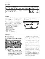
Safety instructions

Warning!

 This must be read!

The laws, ordinances, directives and stand-
ards in force in the country of use are to be
followed (safety regulations, proper recycling
in accordance with the regulations, etc.)
Installation may only be carried out by a quali-
fied electrician. The minimum distances to
other appliances and units are to be ob-
served.
Anti-shock protection must be provided by
the installation, for example drawers may on-
ly be installed with a protective floor directly
underneath the appliance. The cut surfaces
of the worktop are to be protected against
moisture using a suitable sealant.
The sealant seals the appliance to the work
top with no gap. When building in, protect the
underside of the appliance from steam and
moisture, e.g. from a dishwasher or oven.
Avoid installing the appliance next to doors
and under windows. Otherwise hot cook-
ware may be knocked off the rings when
doors and windows are opened.

Warning!

 Risk of injury from electrical

current.

• The electrical mains terminal is live.
• Make electrical mains terminal free of volt-

age.

• Follow connection schematic.
• Observe electrical safety rules.
• Ensure anti-shock protection by installing

correctly.

• The appliance must be connected to the

electrical supply by a qualified electrician.

• Loose and inappropriate plug and socket

connections can make the terminal over-
heat.

• Have the clamping connections correctly

installed by a qualified electrician.
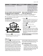
The connection must be carried out as
shown in the diagram, refer to the sticker

on the back of the hob for wiring connec-
tion diagram. The connection links should
be fitted according the appropriate con-
nection diagram. Note for single phase
connection, the link (or bridge) will need to
be fitted between terminals 1 and 2 (refer
to the connection sticker on back of the
unit). The earth lead is connected to ter-
minal 

 .

The earth lead must be longer than leads
carrying electric current.

• Use strain relief clamp on cable.
• In the event of single-phase or two-phase

connection, the appropriate mains cable
of type H05BB-F Tmax 90°C (or higher)
must be used.

• If this appliance’s mains cable is damaged,

it must be replaced by a special cable (type
H05BB-F Tmax 90°C; or higher). Please
contact your local Service Force Center for
further advice.

A device must be provided in the electrical
installation which allows the appliance to be
disconnected from the mains at all poles with
a contact opening width of at least 3 mm
Suitable isolation devices include line pro-
tecting cut-outs, fuses (screw type fuses are
to be removed from the holder), earth leak-
age trips and contactors.

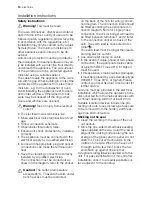
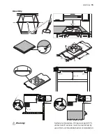
Sticking on the seal

• Clean the worktop in the area of the cut-

out section.

• Stick the one-sided self-adhesive sealing

tape supplied all the way round the lower
edge of the cooking surface along the out-
er edge of the glass ceramic panel. Do not
stretch it. The cut ends should lie in the
middle of one side. When you have cut it
to length (add a few mm), press the two
ends flush up against one another.

A duplicate rating label is supplied with this
unit. For easy identification of this unit after
installation, stick it to a readily available sur-
face adjacent to the cooktop.

Caution!

 The surface temperature

exceeds 95°C. To avoid a hazard, under
bench access must be restricted.

14 

 electrolux

Summary of Contents for EHD68210P

Page 1: ...user manual Ceramic glass induction hob EHD68210P ...

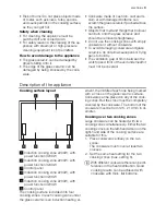
Page 2: ...ren s safety Small children must be kept away from the appliance Only let bigger children work on the appli ance under supervision To avoid small children and pets uninten tionally switching the appliance on we rec ommend activation of the child safety de vice General safety The appliance may only be installed and connected by trained registered service engineers Built in appliances may only be us...

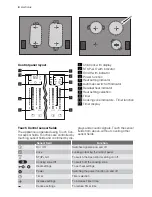
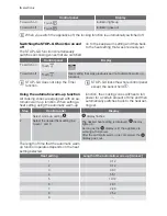
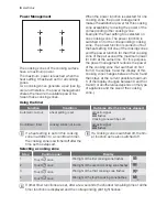
Page 3: ... of the appliance Cooking surface layout 1 5 6 3 4 2 1 Induction cooking zone 2200W with power function 3200W 2 Induction cooking zone 2200W with power function 3200W 3 Control panel 4 Induction cooking zone 2200W with power function 3200W 5 Induction cooking zone 2200W with power function 3200W 6 Control panel The cooking surface is divided into four cooking zones In each cooking zone under the g...

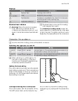
Page 4: ...on trol sensor fields Functions are controlled by touching sensor fields and confirmed by dis plays and acoustic signals Touch the sensor fields from above without covering other sensor fields Sensor field Function On Off Switches appliance on and off Lock Locking unlocking the control panel STOP GO To switch the Keep Warm setting on off Cooking zone Off To switch off the cooking zone Heat setting...

Page 5: ...ware Switching the appliance on and off Control panel Display To switch on Touch for 1 second Indicator lights up The operational readiness indicators of the individual cooking zones also light up To switch off Touch for 1 second Indicator goes out The operational readiness indicators of the individual cooking zones also go out After switching on within approx 10 seconds a heat setting or a functi...

Page 6: ...ing the automatic warm up function All cooking zones are equipped with an au tomatic warm up function When setting a heat setting using the automatic warm up function the cooking zone switches to full power for a certain amount of time and then automatically switches back to the heat set ting set Step Control panel Display 1 Select warm up setting display flashes 2 Select the desired heat setting ...

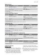
Page 7: ... safety device a heat setting or a function must be set within approx 10 seconds otherwise the appliance automatically switches itself off Switching off the child safety device Step Control panel Pilot light 1 Switch on appliance Do not set a heat setting above lights up 2 Touch for 4 seconds above goes out 3 Switch appliance off The child safety device is switched off Switching the power function...

Page 8: ...d the display of this cooking zone changes between 8 and 5 and then stays at the current possible maximum 5 If the display changes between 8 and 5 or 8 and 3 or another value depends on the type of appliance and the size of the cooking zone Using the timer Function Condition Outcome after the time has elapsed Automatic cut out a heat setting is set acoustic signal 00 flashes Cooking zone switches ...

Page 9: ...ilot light flashes more slowly The time is set The time counts down Displaying the time remaining for a cooking zone Step Control panel field Display 1 Select cooking zone Pilot light of the cooking zone selected flash es faster The time remaining is displayed After a few seconds the pilot light flashes more slowly Switching off the acoustic signal Step Control panel field Acoustic signal 1 Touch ...

Page 10: ...s containing starch may present a health risk due to acryla mide Therefore we recommend cook ing at low temperatures and not brown ing foods too much Cookware for induction cooking zones Cookware material Suitable Steel enamelled steel Cast iron Stainless steel Cookware bottom of multilayer Aluminium copper brass Glass ceramic porcelain Cookware for induction cooking zones is labelled as suitable ...

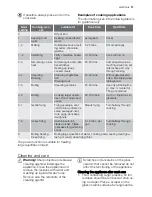
Page 11: ... of food stews and soups 60 150 mins Up to 3 l liquid plus in gredients 6 7 Gentle frying Frying escalope veal cordon bleu cutlets ris soles sausages liver roux eggs pancakes doughnuts Steady frying Turn halfway through cooking 7 8 Heavy frying Hash browns loin steaks steaks Flädle pancakes for garnishing soup 5 15 mins per pan Turn halfway through cooking 9 Boiling Searing Deep frying Boiling lar...

Page 12: ...l panel is wholly or partly covered by objects Remove objects The residual heat indicator is not displaying anything The cooking zone was only on for a short time and is therefore not hot If the cooking zone is supposed to be hot call your local Service Force Centre Repeated acoustic signal 6x appliance switches off One or more sensor fields have been covered for longer than 10 seconds Uncover sen...

Page 13: ...occur at high power levels Clicking 2 during electric switching processes Hissing buzzing 3 The device is fitted with a fan for cooling the electrics A whiring noise can be heard when operating the fan which may deviate depending on the performance and may continue for a while after the appliance is switched off The noises described are normal and do not refer to any defects Disposal The symbol on...

Page 14: ...the hob for wiring connec tion diagram The connection links should be fitted according the appropriate con nection diagram Note for single phase connection the link or bridge will need to be fitted between terminals 1 and 2 refer to the connection sticker on back of the unit The earth lead is connected to ter minal The earth lead must be longer than leads carrying electric current Use strain relie...

Page 15: ...80 1 R5 490 1 min 5 min 5 min 20 min 25 min 5 min 20 min 38 min 5 Warning Surface temperature of base exceed 95 C under bench access must be restricted by use of non combustible barrier or installation electrolux 15 ...

Page 16: ...with your proof of purchase documents in a safe place for future reference should you require service for your Electrolux appliance General Terms and Condi tions 1 In this warranty Electrolux means Electrolux Home Products Pty Ltd ABN 51 004 762 341 in respect of Appliances purchased in Australia and Electrolux NZ Limited in respect of Appliances purchased in New Zealand Appliance means any Electr...

Page 17: ...e in the following situations which are not ex haustive The Appliance is damaged by i accident ii misuse or abuse including failure to properly maintain or service iii normal wear and tear iv power surges electrical storm damage or incorrect power supply v incomplete or improper installation vi incorrect improper or inappropriate operation vii insect or vermin infestation The Appliance is modified...

Page 18: ...ange information in relation to you to enable Electrolux to meet its obligations un der this warranty Important Notice Before Calling a Service Technician please check carefully the operating instructions service booklet and the warranty terms and conditions FOR SERVICE OR TO FIND THE ADDRESS OF YOUR NEAREST STATE SERV ICE CENTRE IN AUSTRALIA Please call 13 13 4 9 For the cost of a local call Aust...

Page 19: ...electrolux 19 ...

Page 20: ...892930417 B 032009 www electrolux com www electrolux com au ...

Reviews: