


TSE-P 02.01 LF
14/35
599 34 60-32
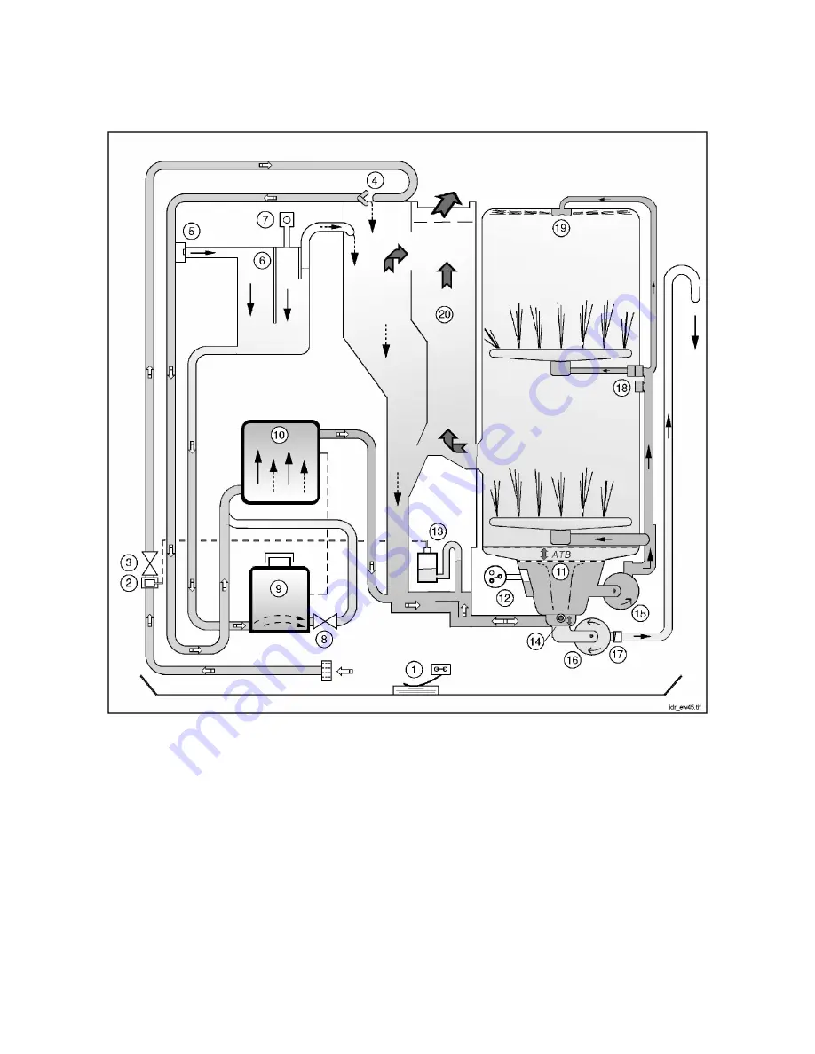
4.5 5. HYDRAULIC
CIRCUIT
KEY
1.
Anti-flooding device
11. Sump
2.
Anti-overflow device
12. Pressure switch
3.
Fill solenoid
13. Connector siphon for anti-overflow device
4.
Air-Break
14. Cutting valve sump
5.
Intake valve for regeneration chamber
15. Wash motor
6.
Regeneration chamber
16. Drain motor
7.
Vent valve 2
nd
regeneration chamber
17. Non-return valve
8.
Regeneration solenoid
18. Delivery valve to upper spray arm
9.
Salt container
19. Upper sprayer
10. Resin reservoir
20. Vent chamber
Summary of Contents for EDW 1000
Page 2: ...TSE P 02 01 LF 2 35 599 34 60 32 ...
Page 27: ...TSE P 02 01 LF 27 35 599 34 60 32 8 ELECTRICAL FUNCTIONS 8 1 CIRCUIT DIAGRAM ...
Page 28: ...TSE P 02 01 LF 28 35 599 34 60 32 8 2 BASIC ELECTRICAL DIAGRAM ...
Page 33: ...TSE P 02 01 LF 33 35 599 34 60 32 9 3 2 COMPONENT CONNECTION DIAGRAM ...