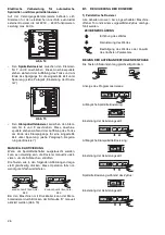
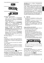
background image

4

WARNING
CAREFULLY  READ  THE  INSTALLATION,  OPERA-
TING 

AND 

MAINTENANCE 

INSTRUCTIONS 

BEFORE  INSTALLING  THIS  APPLIANCE.  INCOR-
RECT  INSTALLATION,  ADAPTATIONS  OR  ALTER-
NATIONS COULD CAUSE DAMAGE TO PROPERTY 
OR  INJURY  TO  PERSONS.  MALICIOUS  DAMAGE, 
DAMAGE DUE TO NEGLIGENCE, OR TO FAILURE 
TO COMPLY WITH INSTRUCTIONS AND REGULA-
TIONS,  OR  TO  INCORRECT  CONNECTIONS  OR 
UNAUTHORISED  TAMPERING  INVALIDATE  ANY 
WARRANTY AND RELIEVE THE MANUFACTURER 
OF ALL LIABILITY.

1. Carefully  read  this  instructions  booklet,  as  it  con-

tains  important  advice  for  safe  installation,  opera-
tion and maintenance.


Keep this booklet to hand in a safe place for future 
reference by other operators.

2. Installation  should  be  carried  out  by  qualified 

engineers,  in  accordance  with  current  regula-
tions and with the manufacturer’s instructions.

3. The appliance should only be used by persons spe-

cifically trained in this operation.

4. Switch  off  the  appliance  in  the  event  of  failure  or 

malfunctioning.

Only have the appliance repaired by a service centre 
authorised  by  the  manufacturer  and  ask  for  original 
spare parts.

A1

HANDLING

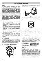
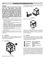
Use suitable means to move the appliance: a lift truck 
or fork pallet trucks (the forks should reach more than 
halfway beneath the appliance).

A2

UNPACKING

Figure 1

Wear protective gloves to unpack.

Lift  the  appliance  using  a  lift  truck,  remove  the  base 
and position the appliance 

Figure 2

where it is to be installed.

Figure 3

Remove the protective film and ensure that the packa-
ging  material  is  disposed  of  correctly  in  compliance 
with the regulations in force in the country where the 
product is to be used.

A3

DISPOSAL

All  the  packaging  materials  are  environment  friendly. 
They may be kept without danger, recycled or burned 
in a special waste incineration plant. Recyclable plastic 
components are marked as follows:

Wood and cardboard components may be disposed of 
according to local regulations in force. Appliances that 
have  reached  the  end  of  their  service  life  should  be 
suitably disposed of. The appliance should be disman-
tled  according  to  regulations  in  force.  All  metal  parts 
are  in  stainless  steel  (AISI  304)  and  are  removable. 
Plastic parts are marked with the symbol of the mate-
rial.

A

GENERAL RECOMMENDATIONS

polyethylene

external wrapping film, 
instruction bag.

polypropyl-
ene

top packaging panels, 
straps

polystyrene 
foam

protective surround ele-
ments.

PE

PP

PS

Summary of Contents for AUCI

Page 1: ...TIANPESUKONE ZUCI AUCI EUCI ZUCIWS AUCIWS EUCIWS ASENNUS KÄYTTÖ JA HUOLTO Sivu 87 NO INNEBYGD OPPVASKMASKIN ZUCI AUCI EUCI ZUCIWS AUCIWS EUCIWS MONTERING BRUK OG VEDLIKEHOLD Side 103 FR LAVE VAISSELLE ZUCI AUCI EUCI ZUCIWS AUCIWS EUCIWS INSTALLATION EMPLOI ET ENTRETIEN Page 119 IT LAVASTOVIGLIE SOTTOTAVOLO ZUCI AUCI EUCI ZUCIWS AUCIWS EUCIWS INSTALLAZIONE USO E MANUTENZIONE Pag 137 ES LAVAVAJILLAS...

Page 2: ......

Page 3: ...tte publication Il Costruttore si riserva il diritto di modificare senza preavviso le caratteristiche delle apparecchiature presentate in questa pubblicazione El Constructor se reserva el derecho de modificar sin previo aviso las características de los aparatos presentados en esta publicación O fabricante reserva se no direito de alterar as máquinas apresentadas nesta publicação sem aviso prévio Ï...

Page 4: ...DE ANGEZEIGTE ALARMMELDUNGEN Pag 25 B4 VORBEREITUNGEN UND DOSIERER FÜR SPÜLMITTEL KLARSPÜLMITTEL Pag 25 B5 REGULIERUNG DER DOSIERER Pag 26 B6 WARTUNG Pag 27 C ANWEISUNGEN FÜR DEN BENUTZER Pag 29 C1 BETRIEBSBEGINN Pag 29 C2 SPÜLGÄNGE Pag 30 C3 BETRIEB Pag 30 C4 BETRIEBSENDE UND TÄGLICHE REINIGUNG Pag 31 C5 UNTERBAUGESCHIRRSPÜLER MIT EINGEBAUTEM DAUER WASSERENTHÄRTER Pag 32 C6 AUF DER BEDIENBLENDE A...

Page 5: ...rätes muß mit Hilfe eines geeigneten Hilfsmittels erfolgen d h mit einem Hub wagen oder Gabelstapler diese müssen breiter sein als die Hälfte der Abmessungen des Produktes A2 ENTFERNUNG DER VERPACKUNG Abb 1 Unter Verwendung von Arbeitshandschuhen die Ver packung entfernen Abb 2 Das Gerät mit einem Hubwagen anheben die Unter lage entfernen und an dem Bestimmungsort aufstel len Abb 3 Den Schutzfilm ...

Page 6: ...Wassers für Modelle ohne eingebauten Dauer Wasserenthärter µS cm 400 400 400 400 Wasserhärte Zufuhr für Modelle mit eingebautem Dauer Wasserenthärter fH dH cH 40 22 4 28 max 40 22 4 28 max 40 22 4 28 max 40 22 4 28 max Chloridkonzentrationen im Wasser ppm 20 20 20 20 Wasserverbrauch pro Klarspülgang l 3 0 7 5 5 9 3 0 3 8 Fassungsvermögen Boiler l 12 12 12 12 Fassungsvermögen Spültank l 23 23 23 23...

Page 7: ...C Abwasseranschlußrohr Innendurchmesser 40 mm int 20 mm I Stromversorgung S Eingang Spülmittelschläuche Q Potentialausgleichsschraube Nur bei Modell mit Fallrohr Nur bei Modell mit Ablaufpumpe 600 508 431 987 69 58 431 403 379 155 612 30 850 750 1000 S A I C Q C A I C S A I Q 820 ...

Page 8: ... Sollte der Druck höher sein ist dem Gerät ein geeigneter Druckminderer vorzuschalten Bei dem Modell mit Fallrohr Das Ablaufrohr C Abb 4 unter Verwendung eines Siphons an die Abflussleitung anschließen oder das Rohr über ein im Fußboden eingelassenes Siphonsieb positionieren Bei dem Modell mit Ablaufpumpe Das Ablaufrohr in einer Höhe von 750 bis 1000 mm vom Boden positionieren Anschließend überprü...

Page 9: ...me Stromversorgung 220 230V 1N Abb 11 Die Klemmenleiste der Versorgung öffnen und die mit gelieferten Überbrückungen wie folgt einsetzen zwei Überbrückungen zwischen den Klemmen Nr 1 3 und 5 und zwei weitere zwischen den Klemmen Nr 2 4 und 6 Mit einem geeigneten Stromversorgungskabel siehe Tabelle Technische Daten jeweils die Phase an die Klemme Nr 5 den Nulleiter an die Klemme Nr 6 und den Erdung...

Page 10: ...t ration von 2g l zu erreichen Bei jedem Zyklus gibt die Pumpe R ca 6g in 6 Sekunden ab Die Betriebszeit der Dosierer kann entsprechend den im anschließenden Paragraphen enthaltenen Anwei sungen verändert werden Das mitgelieferte Rohr in den Spülmittelbehälter ein setzen 2 Geschirrspüler mit eingebauter peristaltischer Klarspülerdosierpumpe Abb 13 Die Pumpe S gibt ca 0 1 g Klarspülmittel pro Sekun...

Page 11: ...Dosierer manuell zu akti vieren um die Schläuch zu entlüften Die Tasten wie in den folgenden Abbildungen darge stellt gleichzeitig drücken Diese Operation falls not wendig mehrfach wiederholen Bei den Maschinen mit Druckboiler kann der Mem brandosierer durch Drücken der Schraube D manuell aktiviert werden Abb 13 B5 REGULIERUNG DER DOSIERER 1 Peristaltische Dosierer Alle Arbeiten müssen bei eingesc...

Page 12: ...l Klarspühlmittel Wenn Sie auf ein anderes Reinigungsmittel Klarspühl mittel umstellen möchten auch wenn dieses von dem selben Hersteller erzeugt wird müssen Sie die Ansaug und Druckschläuche mit frischem Wasser spülen bevor Sie den neuen Reinigungsmittelbehäl ter Klarspühlmittelbehälter anschließen Ansonsten könnte die Mischung von verschiedenen Reinigungs mitteltypen Klarspühlmitteltypen zur Kri...

Page 13: ...S DISPLAYED ON THE CONTROL PANEL Pag 8 B4 DETERGENT RINSE AID DISPENSERS AND SETTINGS Pag 9 B5 SETTING THE DISPENSERS Pag 10 B6 MAINTENANCE Pag 11 C INSTRUCTIONS FOR THE USER Pag 12 C1 STARTING Pag 12 C2 WASH CYCLES Pag 13 C3 OPERATION Pag 13 C4 END OF WORK AND DAILY CLEANING Pag 14 C5 UNDERCOUNTER DISHWASHER WITH INCORPORATED CONTINUOUS WATER SOFTENERPag 15 C6 WARNING MESSAGES DISPLAYED ON THE CO...

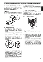
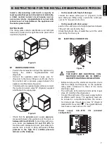
Page 14: ... HANDLING Use suitable means to move the appliance a lift truck or fork pallet trucks the forks should reach more than halfway beneath the appliance A2 UNPACKING Figure 1 Wear protective gloves to unpack Lift the appliance using a lift truck remove the base and position the appliance Figure 2 where it is to be installed Figure 3 Remove the protective film and ensure that the packa ging material is...

Page 15: ...ncorporated continuous water softener µS cm 400 400 400 400 Water supply hardness for models with incorporated water softener fH dH cH 40 22 4 28 max 40 22 4 28 max 40 22 4 28 max 40 22 4 28 max Concentration of chlorides in water ppm 20 20 20 20 Rinse cycle water consumption l 3 0 7 5 5 9 3 0 3 8 Boiler capacity l 12 12 12 12 Tank capacity l 23 23 23 23 Standard cycle time with water supply at 50...

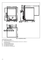
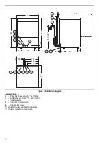
Page 16: ...h ø 3 4 G fittings C Outlet pipe øi 40 mm øi 20 mm I Power supply S Pipe inlet for detergents Q Unipotential screw Only for model with free fall drainage Only for model with drain pump 600 508 431 987 69 58 431 403 379 155 612 30 850 750 1000 S A I C Q C A I C S A I Q 820 ...

Page 17: ...ssure reducer on the inlet pipe On the model with free fall drainage connect the waste outlet pipe C Figure 4 to the main drain pipe fitting a trap or place the outlet pipe over an S trap set into the floor On the model with drain pump position the outlet pipe at a height anywhere between 750 and 1000 mm from the floor Check that about 4 litres of water flow out of the outlet pipe during the rinse...

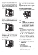
Page 18: ...ply cable see technical data table connect the phase and neutral to terminals 5 and 6 respectively and the earth wire to the terminal Connections provided for energy control This appliance is designed for an external energy con sumption control Figure 12 Connect the energy peak controller across terminals 11 and 12 Safety devices An automatic reset thermoamperometric protective device incorporated...

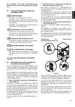
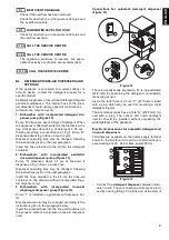
Page 19: ... 0 1 g s of rinse aid It dispenses 0 3 g in 3 sec at each rinse Dispenser operating time may be changed following the instructions given in the next paragraph Insert the hose provided in the kit into the rinse aid container in the versions without incorporated rinse aid dispenser only 3 Dishwashers with incorporated rinse aid diaphragm dispenser pump Figure 13 Pump T is installed in appliances wit...

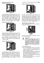
Page 20: ...3 B5 SETTING THE DISPENSERS 1 Peristaltic dispensers All operations should be carried out with the appliance switched on the door open and no cycle selected SEQUENTIAL START Press the indicated buttons simultaneously for 5 seconds Display of programming mode Initial amount of detergent Setting the activation time Initial amount of rinse aid Setting the activation time Amount of detergent during th...

Reviews: