background image

25

5.1.4 GAS PRESSURE REGULATOR

A gas pressure regulator (supplied in a plastic bag with the
appliance)must be installed in an easily accessed posi-
tion ahead of the appliance.

The pressure regulator should preferably be fitted horizontally,
to ensure the right outlet pressure:

1” connection side gas from mains.

2” pressure regulator (3.3"x2.9"x2.7" / 85x75x71mm);

3” connection side gas towards the appliance;

The arrow on the regulator (

) indicates the gas flow

direction.

3

1

2

AUSTRALIA: the gas pressure regulator supplied with the
appliance must be fitted to the appliance inlet. Adjust the
test point pressure with all hob burners operating at maximum
setting as follow:
- 1.0 KPa for Natural gas
- 1.8 KPa for Propane gas

5.1.5. PRIMARY AIR CHECK

When the primary air is correctly adjusted, the flame does
not “float” with burner cold and there is no flareback with
burner hot.

Undo screw “A” and position aerator “C” at distance “H”
given in Table B; retighten screw “A” and seal with paint
(fig. 3A).

5.1.6. CONVERSION TO ANOTHER TYPE OF GAS

Table B “Technical data/gas nozzles” gives the types of
nozzles (contained in a bag supplied with the appliance,
together with the pressure regulator) to be used when
replacing those fitted by the manufacturer; the number is
stamped on the nozzle body. At the end of the procedure,
carry out the following check-list:

Check

Ok

• burner nozzle/s replacement

• correct adjustment of primary air supply to
  burner/s

• pilot nozzle/s replacement

• minimum flame screw/s replacement

• correct adjustment pilot/s if necessary

• correct adjustment of supply pressure  
  (see technical data/gas nozzles table)

• apply sticker (supplied) with data of new gas 
type used

5.1.6.1  MAIN BURNER NOZZLE REPLACEMENT

Remove the control panel.

Unscrew nozzle “C” and replace it with one suitable for
the type of gas (fig.3A) according to that given in Table B.

The nozzle diameter is given in hundredths of mm on the
nozzle body.

Tighten down nozzle “C”.

5.1.6.2 PILOT BURNER NOZZLE REPLACEMENT

Remove the control panel.

Undo screw coupling “H” and replace nozzle “G” with one
suitable for the type of gas (Table B, fig.3b).

The nozzle identification number is given on the nozzle
body.

Retighten screw coupling “H”.

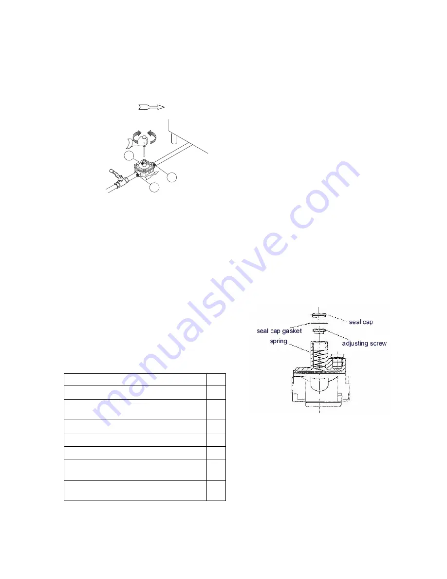
5.1.6.3 REPLACING THE ADJUSTMENT SPRING OF
THE PRESSURE REGULATOR

Replace the spring of the pressure regulator with one
suitable for the gas pressure type given in table B (see
handbook Appendix) as follows:

-

Remove the seal cap, seal cap gasket, adjusting screw
and the spring.

-

Insert the new spring and replace the adjusting screw.

-

Connect a pressure gauge to the appliance’s test point
pressure (fig. 2A/2B).

-

Ignite the appliance’s burners so to have the maximum
gas consumption.

-

Regulate the adjustment screw until the pressure gauge
shows the working pressure value (section 5.1.4 Gas
pressure regulator).

-

Replace the seal cap and gasket and screw tightly closed.

-

Remove the pressure gauge and close the test point
pressure.

-

Prior to operation, test the gas pressure regulator for leaks.


6. BEFORE COMPLETING THE
INSTALLATION OPERATIONS

Use soapy water to check all gas connections for leaks. DO
NOT use a naked flame to check for gas leaks. Light all the
burners individually and also together, to check correct
operation of the gas valves, rings and lighting. For each
burner, adjust the flame regulator to the lowest setting,
individually and together; after completing the operations,
the installer must instruct the user on the correct method of
use. If the appliance does not work properly after carrying
out all the checks, contact the local after-sales service
centre.

Summary of Contents for ARG12FLCE

Page 1: ...3 CLEANING 24 4 DISPOSAL 24 V INSTALLATION 23 1 REFERENCE STANDARDS 23 2 UNPACKING 23 3 POSITIONING 24 4 FUME EXHAUST AND VENTILATION 24 5 CONNECTIONS 24 6 BEFORE COMPLETING INSTALLATION OPERATIONS 25 VI USER INSTRUCTIONS 26 1 FRY TOP USE 26 VII CLEANING 27 1 EXTERNAL PARTS 27 2 OTHER SURFACES 27 3 IDLE PERIODS 28 4 INTERNAL PARTS 28 VIII MAINTENANCE 28 1 MAINTENANCE 28 ...

Page 2: ...ARG24FLCEP 169073 ARG24RRCEP 610mm 24 169052 ARG36FLCE 169068 ARG36FLCEP 169074 ARG36RRCEP 915mm 36 169054 ARG12FRCE 305mm 12 TECHNICAL DATA 169050 ARG12FLCE 305mm 12 BSP connection Ø 3 4 3 4 3 4 3 4 3 4 3 4 3 4 3 4 Burners Nr 1 2 3 4 1 2 3 4 Btu h 21800 43600 65400 87200 21800 43600 65400 87200 MJ h 23 46 69 92 23 46 69 92 169055 ARG24FRCE 610mm 24 Nominal heat output 169056 ARG36FRCE 915mm 36 16...

Page 3: ...heir safety Personnel using the appliance must be trained Do not leave the appliance unattended when in use Turn the appliance off in case of a fault or poor operation Do not use products even if diluted containing chlorine sodium hypochlorite hydrochloric or muriatic acid etc to clean the appliance or the floor under it Do not use metal tools to clean steel parts wire brushes or Scotch Brite type...

Page 4: ...on to another type of gas must only be carried out by qualified personnel authorised by the manufacturer Failure to observe the correct installation conversion and modification procedures can result in damage to the appliance danger for people and invalidates the Manufacturer s warranty 1 REFERENCE STANDARDS This appliance must comply with the applicable federal state or local regulations These in...

Page 5: ... danger to people ForAustralia ventilationmustbeinaccordancewithaustralian building codes and kitchen exhaust hoods must comply with AS NZS1668 1 and AS 1668 2 5 CONNECTIONS Any installation work or maintenance to the supply system must only be carried out by the utility company or an authorised installer Refer to the appliance dataplate for the product code See the installation diagram for the ty...

Page 6: ... BURNER NOZZLE REPLACEMENT Remove the control panel Unscrew nozzle C and replace it with one suitable for the type of gas fig 3A according to that given in Table B The nozzle diameter is given in hundredths of mm on the nozzle body Tighten down nozzle C 5 1 6 2 PILOT BURNER NOZZLE REPLACEMENT Remove the control panel Undo screw coupling H and replace nozzle G with one suitable for the type of gas ...

Page 7: ... 36 it consists of three cooking zones left middle and right side controlled by three thermostatic gas valves one for each zone The bulbs for measuring the temperature are located in the middle of each sector left middle and right side respectively Frytop 1220mm 48 it consists of four cooking zones from left to right controlled by four thermostatic gas valves one for each zone The bulbs for measur...

Page 8: ...ng a damp cloth or in case of encrustations the accessories optional or supplied specified in the list After cleaning switch the appliance on to dry the surface quickly then lightly lubricate the surface with cooking oil 1 2 GAS MODELS WITH PILOT IGNITION B A 210 210 240 240 180 180 150 150 120 120 90 90 C 260 260 C SWITCHING ON The thermostatic valve control knobs have the following positions Kno...

Page 9: ...never it is not perfectly sharp COLLECTIONTRAYS ANDTANKS even several times a day Remove any grease oil food residuals etc from tanks trays and containers in general used for collection Always clean the containers at the end of the day While using the appliance empty them when they are nearly full 3 IDLE PERIODS If the appliance is not going to be used for some time take the following precautions ...

Page 10: ...e the component FRYTOP MAIN BURNER Remove the knobs and control panel Remove the clamp fixing the burner to the gas pipe and nozzle holder Unscrew the pilot and thermocouple pipe Unscrew and remove the main burner closing sheet Remove the burner and replace it For installation carry out the same procedure in reverse order 1 2 MAINTENANCE SCHEDULE It is advisable to have the appliance inspected by ...

Reviews: