


WARM & SERVE DRAWER INSTALLATION INSTRUCTIONS
2
c
/
c
25
5
/
16
"
(64.3 cm)
24" (64.3 cm) Max.
23
5
/
8
" (60 cm) Min.
c
/
c
12
21
/
32
"
(32.15 cm)
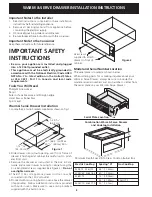
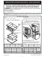
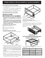
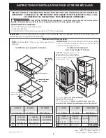
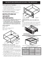
Figure 1
Important Notes to the Installer
1.
Read all instructions contained in these installation
instructions before installing appliance.
2.
Remove all packing material from appliance before
connecting the electrical supply.
3.
Observe all governing codes and ordinances.
4.
Be sure to leave these instructions with the consumer.
Important Note to the Consumer
Keep these instructions for future reference.
IMPORTANT SAFETY
INSTRUCTIONS
•
Be sure your appliance is installed and plugged
into a 120 Volt grounded outlet.
•
This appliance must be electrically grounded in
accordance with the National Electrical Code ANSI/
NFPA No. 70—latest edition in the United States,
or CSA C22.1, Part 1 in Canada, and local code
requirements.
Tools You Will Need
Phillips® Screwdriver
Pencil
Ruler or Tape Measure and Straight-edge
Hand Saw or Saber Saw
Spirit Level
Warm & Serve Drawer Installation
1.Locate the 2 anti-tip brackets supplied as shown on fig. 1.
Figure 2
Use screws
supplied to attach
drawer to front of
cabinet.
Combination Warm & Serve Drawer
and Cooktop Installation
A
Minimum Depth Spacing To Clear Cooktop Burner Box
2.Slide drawer into cutout opening until front frame of
drawer is flush against cabinet. Be careful not to pinch
electrical cord.
3.Remove the drawer as instructed in the Use & Care
Guide and secure drawer housing to cabinet using the
3 nickel-plated screws supplied (see Figure 2).
Do not
overtighten screws.
4.The 60" (152 cm) appliance power cord can now be
connected into the 120 Volt outlet.
5.Proceed with mounting built-in oven above the drawer
(if applicable). Follow installation instructions provided
with built-in oven. Make sure to use anti-tip brackets
supplied with the built-in oven.
Model and Serial Number Location
The serial plate is located as shown below.
When ordering parts for or making inquiries about your
Warm & Serve Drawer, always be sure to include the
model and serial numbers and a lot number or letter from
the serial plate on your Warm & Serve Drawer.
Serial Plate Location
Electric Cooktop
E30IC75, E36IC75
E30EC65, E36EC65
E36EC75
E30EC70, E36EC70
Gas Cooktop
E36GC75
Spacing "A"
4.5" (11.43cm)
6.0" (15.24cm)
7.5" (19.05cm)
8.5" (21.59cm)
5.0" (12.7cm)